TM-9-2320-273-34 - Page 709 of 801
TM 9-2320-273-34
(3)
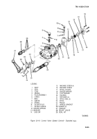
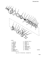
Remove the handle (27) by disassembling the pin kit (24).
(4)
Remove the four machine screws (15) and the end cap (14).
(5)
Remove the machine screw (16) from the end of the spool (23
(13,) (17), (12), (19), (23), (20), (22), (21), and (18) to be removed.
, This allows items
(6)
Remove the two screws (26) from the body (1). Remove handle bracket
(25), retainer (21), and spool seal (22).
(7)
Remove plug assembly (5), O-ring (6), spring (4), cone (3) and seal (2).
(8)
Remove the relief valve (28) and seal kit (29).
(9)
Remove the detent plug (10), spring (9), ball (7), and detent sleeve (8) from the
housing (20). Inspect for spring damage and moisture contamination.
(lo)
Inspect the relief valve (28) for damage and contamination.
(17)
Inspect all parts for wear and signs of damage. If the spool (23) or body (1) are worn or
pitted, the valve must be replaced.
c.
Assembly.
NOTE
Replace all seals.
(1)
install the plug assembly (5), O-ring (6), spring (4), cone (3), relief valve (28) and
seal kit (29)
(2)
Install the spool (23).
(3)
Install the detent subassembly: items (13), (17), (12), (19), (11), (23), (20), (22), (21),
and (18). Secure with machine screw (16). Torque to 8 Ib-ft (11 N•m).
(4)
(5)
(6)
Install the ball (7), spring (9), and detent plug (10) in the housing (20).
Install handle bracket (25), screws (26) in body (1). Torque to 8 Ib-ft (11 NŽm).
Install the handle (27) and secure it with the pin kit (24)
(7)
Install the end cap
(14)
and four machine screws (15). Tighten the machine screws to
8 Ib-ft (11 NŽm) torque.
20-7. Repair of Control Valve (Directional Rotation).
a. Removal. (Refer
to TM 9-2320-273-20.)
b. Disassembly.
(1)
Clean the outside of the valve thoroughly.
(2)
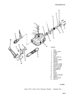
Clamp the valve body (16, fig. 20-20) in a vise.
20-26
Back to Top

