TM-9-2320-273-34 - Page 734 of 801
TM 9-2320-273-34
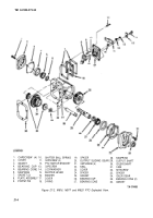
21-5. Disassembly of PTO (M918).
a.
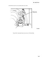
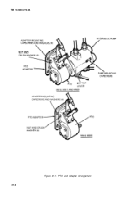
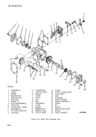
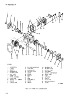
Remove six nuts and crush washers that fasten the PTO to the adapter (fig. 21-1). Separate the
PTO and the adapter. Remove gasket (38, fig. 21-3) from case (30).
b.
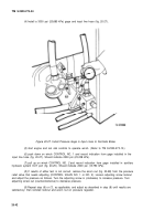
Remove three capscrews (11) from cover (17). (The fourth capscrew (11) was removed during
the PTO cable removal procedure). Remove PTO switch bracket (12).
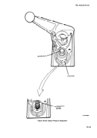
c. Remove capscrew (13) and Iockwasher (14) that fastens the shifter lever (15) to the cover. Mark
the lever and the spindle so that they can go back together in the same position. Pull off the lever (15),
washer (16) and cover (17). Remove O-ring (18). Remove plate subassembly (8).
d.
1 Remove poppet pin (9) and shifter ball spring (10), if required.
e.
Remove two gaskets (7).
f.
Back out setscrew (31) flush to surface of case (30).
g.
Press out idler shaft (29). Remove two thrustwashers (32) and (39) and input sliding gear (37)
with sleeve (36), needle bearings (33) and spacer (34) still inside. Carefully remove spacer and needle
bearings (17 per set, 34 total) and keep in sets if possible.
h.
Press sleeve (36) out of input sliding gear (37) and remove key (35).
.
Remove four capscrews (1) and carefully pry off cover (2) with attached bearing cup (4).
Remove gasket (3) and press out bearing cup, if required.
i.
Remove key (19) from end of output shaft (26). Remove four capscrews (21) and carefully
pry off cover (22) with seal (20) and bearing
CUP
(24) attached. Remove gasket (23). If required, pry
out seal and press out bearing cup.
k.
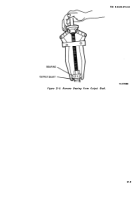
Using a suitable bearing puller, remove bearing cone (5) from end of output shaft (26). (See
fig. 21-5).
/. Remove snapring (6) and pull output shaft (26) out from opposite end of case (30). Remove
spacer (27).
m
Remove bearing cone (25) with a suitable puller.
n.
Pull output sliding gear (28) out of case (30).
21-5
Back to Top

