TM-9-2320-273-34 - Page 743 of 801
TM 9-2320-273-34
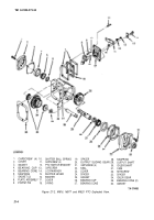
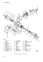
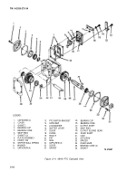
21-11. Reassembly of PTO (M919).
a.
position output sliding gear (29, fig. 21-4) and output shaft (27) in case (31).
b.
Install snapring (6) and (28) on each end of the output shaft.
c.
press bearing cones (5) and (26) onto output shaft.
d.
If removed, install bearing cup (25) and seal (21) into cover (23).
e.
InstalI cover (23) and new gasket (24) to case (31) with four capscrews (22). Tighten cap-
screws to 17 Ib-ft (23 N•m) torque.
f.
If removed, install bearing cup (4) into cover (2).
g.
Install cover (2) and new gasket (3) to case (31) with four capscrews (1). Tighten capscrews
to 17 Ib-ft (23 N•m) torque.
h.
Position idler gear (34), two bearing cones (35) and spacer (33) in case (31). Use same thick-
ness spacer(s) as removed.
i.
Press idler shaft (30) into case (31 ) with flat on shaft positioned in line with setscrew hole
in case.
j.
Install setscrew (32) to secure idler shaft (30).
k.
If removed, install shifter ball spring (10) and poppet pin (9) into cover (17).
l.
Install new O-ring (18) onto plate subassembly (8). Install plate subassembly (8), washer (11),
shifter lever (16), Iockwasher (15) and capscrew (14) to cover (17). Aline marks made during disassembly
and tighten capscrew to 17 Ib-ft (23 N•m) torque.
m.
Position cover (17), two new gaskets (7) and spacer (19) to case (31). Install two capscrews
(12) to upper left and lower right holes finger tight. position PTO switch bracket (13) mounting hole
to lower left hole and install capscrew (12). Torque three capscrews (12) to 17 Ib-ft (23 NŽm). The
fourth capscrew (12) will be installed in the upper right hole during the PTO cable installation pro-
cedure.
n.
Install key (20) into output shaft (27) and secure with tape.
21-14
Back to Top

