TM-9-2320-273-34 - Page 745 of 801
TM 9-2320-273-34
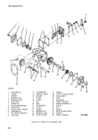
21-13. Install ation of PTO (M916, M917 and M920).
a.
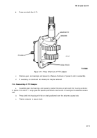
Install gasket (36, fig. 21-2) on PTO adapter and mount PTO. Secure PTO to adapter with
six nuts and six new crush washers. Tighten nuts to 35-40 Ib-ft (48-54 N•m) torque.
b.
Using a dial indicator, check backlash of small gear assembly as described in para 21-12. Adjust
backlash by changing thickness of gasket (36).
c.
Install PTO cable. (Refer to TM 9-2320-273 -20.)
d.
Install pump, with hydraulic lines inplace, as follows:
(1)
Aline spline.
(2)
Secure pump to PTO with two capscrews (M916 and M920) or four capscrews (M917).
Tighten capscrews to 50 Ib-ft (68 N•m) torque.
e.
Install PTO switch. (Refer to TM 9-2320-273 -20.)
21-14. Installation of PTO (M918).
a.
Install gasket (38, fig. 21-3) on PTO adapter and mount PTO. Secure PTO to adapter with
six nuts and six new crush washers. Tighten nuts to 35-40 Ib-ft (48-54 NŽm) torque.
b.
Using a dial indicator, check backlash of gear as described in para 21-12c. Adjust backlash by
changing thickness of gasket (38).
c.
Install PTO cable. (Refer to TM 9-2320-273 -20.)
d.
Remove tap securing key (19) and install drive shaft. (Refer to TM 5-3895-371-24 & P).
e.
install PTO switch. (Refer to TM 9-2320 -273-20.)
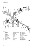
21-15. Installation of PTO (M919).
a. Install
gasket (36, fig. 21-4) on PTO adapter and mount PTO. Secure PTO to adapter with
six nuts and six new crush washers. Tighten nuts to 35-40 Ib-ft (48-54 N•m) torque.
b.
Using a dial indicator, check backlash of small gear as described in para 21-12c. Adjust back-
lash by changing thickness of gasket (36).
c.
Install PTO cable. (Refer to TM 9-2320-273 -20.)
d.
Remove tape securing key (20) and install driveshaft. (Refer to TM 5-3895-372-20).
e.
Install PTO switch. (Refer to TM 9-2320-273-20.)
21-16
Back to Top

