TM-9-2320-279-20-1 - Page 740 of 985
TM 9-2320-279-20-1
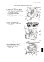
Electrical System Maintenance instructions (Cont)
b. Installation.
NOTE
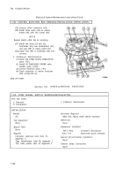
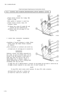
There are two kinds of flasher relays. Model A is round and is strapped to wire harness
with a plastic cable tie; Model B is square and is attached to the dash with a screw,
lockwasher, and nut. If a Model A relay must be replaced by a Model B relay, the top left
side hole in the headlight guard must be drilled out and the self-tapping screw replaced by
a screw, lockwasher, and nut. Also, a ground wire must be added. Route the ground wire
along the wire harness to the ground point on the ignition switch bracket. Refer to
TM 9-2320-279-24P for proper identification of parts. For Model A, do steps
(1)
through
(3).
For Model B, do steps
(4)
through
(7).
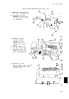
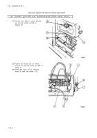
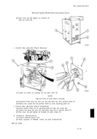
(1)
Install flasher relay (1) in base (2).
(2)
Secure flasher relay (1) to wire harness (3) with plastic cable tie (4).
(3)
Install instrument panel (5) with six screws (6).
(4)
Connect electrical connector (7) to flasher relay (8).
(5)
Position headlight guard (9) and relay (8) in appropriate area under driver-side dash panel.
(6)
Install screw (10), relay (8), ground wire (11), lockwasher (12), and nut (13).
(7)
Install three screws (14).
c. Follow-on Maintenance.
(1)
Connect batteries (para 7-91).
(2)
Check operation of turn signals (TM 9-2320-279-10).
END OF TASK
7-52.
DELETED.
Change 3
7-170.1/(7-170.2 blank)
Back to Top

