TM-9-2320-280-20-2 - Page 516 of 951
4-114. 200 AMPERE REGULATOR (A0013036AA) REPLACEMENT
This task covers:
a. Removal
b. Installation
INITIAL SETUP:
Applicable Models
M996, M996A1, M997, M997A1
Tools
General mechanic’s tool kit:
automotive (Appendix B, Item 1)
Materials/Parts
Four lockwashers (Appendix G, Item 138)
Six lockwashers (Appendix G, Item 142)
Four lockwashers (Appendix G, Item 143)
Manual References
TM 9-2320-280-10
TM 9-2320-280-24P
Equipment Condition
• Battery ground cable disconnected (para. 4-73).
• Hood raised and secured (TM 9-2320-280-10).
1.
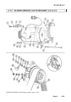
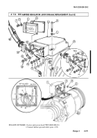
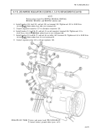
Remove four screws (1), lockwashers (2), cover (3), and gasket (4) from regulator (5). Discard
lockwashers (2).
NOTE
Prior to removal, tag leads for installation.
2.
Remove nut (13), lockwasher (12), washer (11.1), and lead 2A (11) from stud (9). Discard
lockwasher (12).
3.
Remove nut (15), washer (16), and lead 5A (14) from stud (10).
4.
Remove rubber wedge (17) from opening in regulator (5).
5.
Remove four screws (6) and lockwashers (7) from regulator (5) and alternator (8) and pull regulator
(5) away for access to leads (21). Discard lockwashers (7).
6.
Remove five screws (23), lockwashers (22), leads (21), and regulator (5) from alternator (8). Discard
lockwashers (22).
7.
Remove nut (19) and lead 568A (20) from stud (10).
1.
Install lead 568A (20) on stud (10) with nut (19).
2.
Install five leads (21) on regulator (5) with five lockwashers (22) and screws (23).
3.
Install regulator (5) on alternator (8) with four lockwashers (7) and screws (6).
4.
Install lead 5A (14) on stud (10) with washer (16) and nut (15).
5.
Install lead 2A (11) on stud (9) with washer (11.1), lockwasher (12), and nut (13).
6.
Install rubber wedge (17) in opening in regulator (5).
7.
Install gasket (4) and cover (3) on regulator (5) with four lockwashers (2) and screws (1).
b. Installation
a. Removal
TM 9-2320-280-20-2
4-270
Change 3
Back to Top

