TM-9-2320-280-20-2 - Page 522 of 951
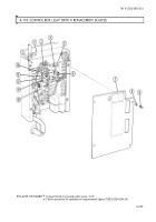
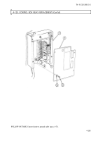
4-117. CONTROL BOX FUSE BLOCK AND RELAY SOCKET REPLACEMENT
This task covers:
a. Removal
b. Installation
a. Removal
1.
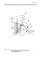
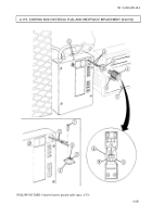
Remove two tiedown straps (3) from fuse block leads (7). Discard tiedown straps (3).
2.
Remove two plain-assembled nuts (6), washers (5), and screws (2) from fuse block (4) and control
box (1) and pull fuse block (4) away for access to leads (7). Discard plain-assembled nuts (6).
b. Installation
1.
Connect six leads (7) to fuse block (4).
2.
Install fuse block (4) on control box (1) with two screws (2), washers (5), and plain-assembled
nuts (6).
3.
Install fuse block leads (7) with two tiedown straps (3).
Manual References
TM 9-2320-280-10
TM 9-2320-280-24P
Equipment Condition
• Control box removed (para. 4-96 or 4-97).
• If replacing a fuse block: remove fuses
(TM 9-2320-280-10).
• If replacing relay socket: remove relays
(para. 4-120).
TM 9-2320-280-20-2
4-276
Change 3
NOTE
Procedures for replacing the upper fuse block, and relay socket
are basically the same. This procedure covers replacement of the
lower fuse block.
NOTE
Prior to removal, tag leads for installation.
3.
Disconnect six leads (7) from fuse block (4) and remove fuse block (4).
INITIAL SETUP:
Applicable Models
M996, M996A1, M997, M997A1, M997A2
Tools
General mechanic’s tool kit:
automotive (Appendix B, Item 1)
Materials/Parts
Two plain-assembled nuts
(Appendix G, Item 201)
Two tiedown straps (Appendix G, Item 308)
Back to Top

