TM-9-2320-280-20-2 - Page 556 of 951
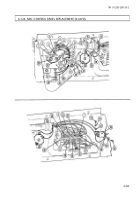
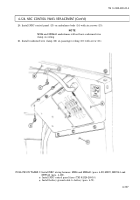
4-126. HEAT/VENT CONTROL PANEL RELAY AND SWITCH MAINTENANCE
(M996, M996A1)
This task covers:
a. Heater Run-Start Switch Removal
i.
Spot Vent Switch Removal
b. Heater Run-Start Switch Installation
j.
Spot Vent Switch Installation
c. 24-Volt Relay Removal
k.
Fuel Hi-Low Switch Removal
d. 24-Volt Relay Installation
l.
Fuel Hi-Low Switch Installation
e. Relay Socket Removal
m. Fan Hi-Low Switch Removal
f.
Relay Socket Installation
n.
Fan Hi-Low Switch Installation
g. Heat On Light Removal
o.
Rollover Switch Removal
h. Heat On Light Installation
p.
Rollover Switch Installation
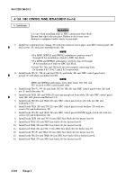
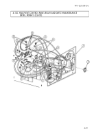
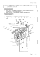
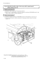
a. Heater Run-Start Switch Removal
1.
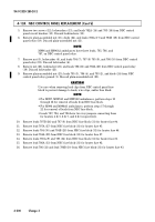
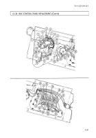
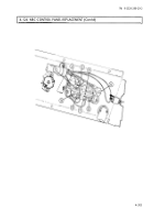
Remove nut (8), switch (4), washer (6), and nut (5) from panel (7).
2.
Remove six screws (1), lockwashers (3), and seven terminals (2) from switch (4). Discard
lockwashers (3).
b. Heater Run-Start Switch Installation
1.
Install seven terminals (2) on switch (4) with six lockwashers (3) and screws (1).
2.
Install nut (5), washer (6), and switch (4) on panel (7) with nut (8).
Manual References
TM 9-2320-280-24P
Equipment Condition
• Battery ground cable disconnected (para. 4-73).
• Heater compartment panel removed
(para. 11-204).
• Heat/vent control panel removed (para. 4-125).
TM 9-2320-280-20-2
4-310
Change 3
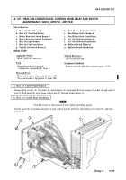
NOTE
Prior to removal, tag leads for installation.
INITIAL SETUP:
Applicable Models
M996, M996A1
Tools
General mechanic’s tool kit:
automotive (Appendix B, Item 1)
Materials/Parts
Twenty lockwashers
(Appendix G, Item 169)
Three plain-assembled nuts
(Appendix G, Item 201)
Back to Top

