TM-9-2320-280-20-2 - Page 697 of 951
6 - 2 9 . LOWER CONTROL ARM REPLACEMENT
( C o n
t ' d )
TM 9-2320-280-20-2
Change 2
6 - 6 5
FOLLOW-ON TASKS: • Install shock absorber (para. 6-31).
• Check wheel alignment (paras. 8-10 and 8-11).
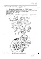
NOT E
Ensure outer capscrews on front ball joints are installed from top down and
inner capscrews are installed from bottom up for M1123 and
“A2” series.
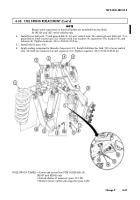
4.
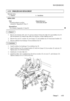
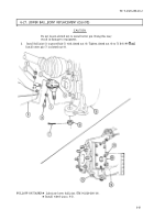
Install geared hub (4) and ball joint (5) on lower control arm (8) with four washers (6), capscrews (9),
washers (6), and locknuts (7). Tighten locknuts (7) to 35 lb-ft (47 N
•
m).
5.
Tighten locknuts (3) to 260 lb-ft (352 N
•
m).
6.
Install wheel (para. 8-3).
7.
Apply sealing compound to threads of capscrew (14). Install bar link (13) to lower control arm (8),
with two washers (12) and capscrew (14). Tighten capscrew (14) to 70 lb-ft ( 95 N
•
m).
Back to Top

