TM-9-2320-280-34 - Page 39 of 1258
TM 9-2320-280-34
Table 2-1. Mechanical Troubleshooting (Cont ’d)
MALFUNCTION
TEST OR INSPECTION
29.
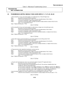
TRANSMISSION CONTROL MODULE (TCM) CODES ARE 59, 71, 75, 79, 81, 82, 83
a. Shift solenoid A (1-2) may not function properly (1st and 4th gear only, 2nd and 3rd gear only).
Step 1.
Disconnect transmission electrical connector.
Step 2.
Check resistance between pins A and E, resistance should be between 18 to 24 ohms.
Step 3.
If resistance at connector is high or low proceed to step 4.
Step 4.
Check wires to solenoid for open short ci
rcuit and check for bad connections replace internal harness
(para. 17-14) if ok proceed to step 5.
Step 5.
Replace solenoid (para. 17-28).
END OF TESTING!
b. Shift solenoid B (2-3) may not function properly (lst and 2nd only, 2nd gear only, 3rd and 4th gears only).
Step 1.
Disconnect transmission electrical connector.
Step 2.
Check resistance between pins B and E, resistance should be between 18 to 24 ohms.
Step 3.
If resistance at connector is high or low proceed to step 4.
Step 4.
Check wires to solenoid for open or short circuits and bad connections, or replace internal harness
(para. 17-14) if ok proceed to step 5.
Step 5.
Replace solenoid (para. 17-28).
END OF TESTING!
c. Force motor (pressure control solenoid) may not function properly (harsh shifting and soft shift).
Step 1.
Disconnect transmission electrical connector.
Step 2.
Check resistance between pins C and D resistance should be between 3.5 to 5.0 ohms.
Step 3.
If resistance at connector is high or low proceed to step 4.
Step 4.
Check wires to solenoid for open or short circuits and bad connections, or replace internal harness
(para. 17-14) if ok proceed to step 5.
Step 5.
Replace solenoid (para. 17-28).
END OF TESTING!
d. Torque converter clutch solenoid (no fourth gear, or clutch stuck on).
Step 1.
Disconnect transmission electrical connector.
Step 2.
Check resistance between pins S and E, resistance should be between 10 to 14 ohms.
Step 3.
If resistance at connector is high or low proceed to step 4.
Step 4.
Check wires from connector to solenoid for breaks or shorts, or replace internal harness
(para. 17-14) if ok proceed to step 5.
Step 5.
Replace solenoid (para. 17-28).
END OF TESTING!
e. Transmission fluid temperature sensor may not function properly (incorrect TCC apply and release).
Step 1.
Disconnect transmission electrical connector.
Step 2.
Using a multimeter check resistance between pins M and L (the resistance should be high at low
temperatures and low at high temperatures).
(a) The resistance at connector at 0 °C (320F) should be less than 11000 ohms and more than 7800 ohms.
(b) The resistance at connector, at 20 °C (680F) should be less than 4100 ohms and more than 2900 ohms.
(c) The resistance at connector, at 40 °C (104 °F) should be less than 1700 ohms and 1200 ohms.
(d) The resistance at room temperature (72 °F) should be between 2500 and 5000 ohms
If any of the above conditions are not met, replace transmission fluid temperature sensor (para. 17-28).
Step 3
Check wires from connector to sensor for breaks or shorts,
or replace internal harness (para. 17-14).
END OF TESTING!
2-13
Back to Top


