TM-9-2320-280-34 - Page 33 of 1258
TM 9-2320-280-34
Table 2-1.
Mechanical Troubleshooting (Cont'd)
MALFUNCTION
TEST OR INSPECTION
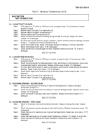
Step 9.
Check transmission case for internal damage or porosity. Replace transmission (para. 7-6) if
case is damaged or porous.
Step 10. Inspect control valve for nicks on machined surfaces or voids in casting; check 1-2
accumulator valve train for stuck valves or incorrect assembly; check front accumulator piston
and oil seal rings for damage.
Replace control valve (chapter 17) if any damage is found.
Step 11. Check rear servo and rear accumulator pistons and oil seal rings for damage. Repair rear servo
(para. 17-11) if damaged.
Step 12. Check center support bolt for looseness. Tighten to 20-25 lb-ft (27-34 N.m).
WARNING
Compressed air used for cleaning purpose will not exceed 30 psi (207
kPa). Use only with effective chip guarding and personnel protective
equipment (goggles, shield, gloves, etc.).
Step 13. Air check intermediate clutch piston for proper operation. If operation is normal, proceed to
step 14. If piston exhibits excessive leakage, proceed to step 15.
Step 14. Check intermediate clutch piston, plates, and release springs for damage or incorrect
assembly. Repair intermediate clutch piston (para. 17-18) if damaged.
Step 15. Check center support for missing orifice plug. Replace transmission (para. 76) if plug is
missing.
END OF TESTING!
18.
1-2 SHIFT FIRM OR ROUGH
Step 1.
Perform steps 7 through 10 of malfunction 16.
Step 2.
If oil pressure in "D" (drive) at 1000 rpm is normal, proceed to step 3. If oil pressure is high,
proceed to step 7.
Step 3.
Check 1-2 accumulator valve train for stuck valves or incorrect assembly. Replace control
valve (chapter 17) if any damage is found.
Step 4.
Check rear accumulator piston and oil seal rings for damage. Repair rear servo (para. 17-11) if
damaged.
Step 5.
Check transmission case for restricted oil passages, damage, or porosity. Remove obstructions
or replace transmission (para. 7-6) if case is damaged or porous.
Step 6.
Check for missing or incorrectly installed check balls. Replace missing check balls (chapter
17).
Step 7.
Check for damaged detent solenoid. Using multimeter, test solenoid coil resistance. Resistance
should be 60-70 ohms. Replace solenoid (chapter 17) if damaged.
Step 8.
Check control valve spacer plate for obstructions and damaged or misalined gasket. Clean or
replace spacer plate (chapter 17).
Step 9.
Check detent valve train for stuck valves or incorrect assembly. Replace control valve (chapter
17) if damaged.
Step 10. Check oil pump for obstructed oil passages or damage. Repair oil pump (para. 17-6) if
damaged.
END OF TESTING!
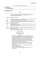
19.
NO 2-3 UPSHIFT OR DELAYED UPSHIFT
NOTE
If malfunction only occurs at or near full throttle, check engine timing for
proper adjustment and check exhaust system for restrictions.
Step 1.
Perform steps 7 through 10 of malfunction 16.
Step 2.
Check control valve for a stuck 2-3 valve, and misaligned or damaged gaskets. Replace
control valve (chapter 17) if damaged.
Step 3.
Check direct clutch for damage or burned clutch plates. Repair direct clutch (para. 17-8) if
damaged.
2-9
Back to Top

