TM-9-2320-280-34 - Page 32 of 1258
TM 9-2320-280-34
Table 2-1.
Mechanical Troubleshooting (Cont'd)
MALFUNCTION
TEST OR INSPECTION
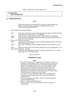
TRANSMISSION (3L80)
NOTE
•
In the event of a major transmission malfunction involving the torque
converter or oil pump, replace filter, flush oil cooler and lines before
replenishing fluid.
•
· Perform the oil pressure tests (para. 17-32) and record the readings for use
during troubleshooting.
•
· Perform a road test (TM 9-2320-280-20).
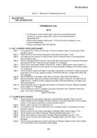
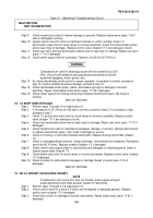
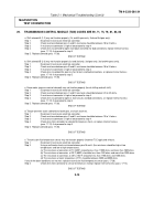
16.
NO 1-2 UPSHIFT OR DELAYED UPSHIFT
Step 1.
If oil pressure in D )"(drive) at 1000 rpm is normal, proceed to step 2. If oil pressure is high,
proceed to step 3.
Step 2.
Check results of control valve and governor line pressure test (para. 17-32).
Step 3.
If oil pressure in N' (neutral) at 1000 rpm was normal, proceed to step 4. If oil pressure was
high, proceed to step 7.
Step 4.
Check for damaged detent solenoid. Using multimeter, test solenoid coil resistance. Resistance
should be 60-70 ohms. Replace solenoid (chapter 17) if damaged.
Step 5.
Check control valve spacer plate for obstructions. Clean or replace spacer plate (chapter 17).
Step 6.
Check detent valve train for stuck valves or incorrect assembly. Replace control valve (chapter
17) if necessary.
Step 7.
Check modulator cable and linkage for damage or obstruction to movement. Cable core should
move freely in its housing, replace modulator (TM 9-2320-280-20) or linkage (TM 9-2320-280-
20) if damaged.
Step 8.
Check adjustment of modulator cable. Adjust modulator cable (TM 9-2320-280-20).
Step 9.
Remove modulator cable at transmission and measure depth of cable pin. Pin depth must be
0.590-0.700 in. (14.98-15.24 mm). Replace modulator (TM 9-2320-280-20) if pin depth is not
within specifications.
Step 10. Check modulator valve for damage and freedom of movement in its bore. Replace modulator
valve (chapter 17) if damaged.
Step 11. Check transmission case for damage or porosity at modulator valve. Replace transmission
(para. 7-6) if case is damaged or porous.
END OF TESTING!
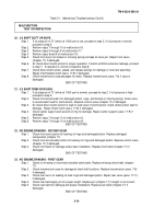
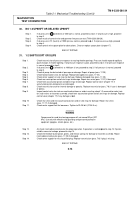
17. 1-2 SHIFTS SOFT OR SUPS
Step 1.
Check transmission oil pressure response to varying throttle openings. Pressure should
respond rapidly to quick changes in throttle opening. If oil pressure response is poor, proceed
to step 2. If oil pressure response is normal, proceed to step 3.
Step 2.
Perform steps 7 through 10 of malfunction 16.
Step 3.
If oil pressure in ED" (drive) at 1000 rpm is low, proceed to step 4. If oil pressure is normal,
proceed to step 10.
Step 4.
Check oil pump for obstructed oil passages or damage. Repair oil pump (para. 17-6).
Step 5.
Check forward clutch seals for damage. Replace damaged seals (para. 17-7).
Step 6.
Check center support oil seal rings for damage. Replace damaged rings (par. 17-9).
Step 7.
Check rear servo piston and oil seal rings for damage. Repair rear servo (para. 17-11) if
damaged.
Step 8.
Check front-accumulator piston and oil seal rings for damage. Replace control valve (chapter
17) if accumulator piston components are damaged.
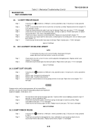
2-8
Back to Top

