TM-9-2320-280-34 - Page 529 of 1258
10-5.
REAR PA R K
I N G BRAKE CALIPER REPA
I R
TM 9-2320-280-34
1 0 - 8
Change 1
INITIAL SETUP:
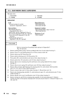
To o l s
____
General mechanic’s tool kit:
automotive (Appendix G, Item 1)
M a t e r i a l s / P a rt s
_____________
Rear brake caliper kit
(Appendix E, Item 137.1)
Brake fluid, silicone (Appendix B, Item 9)
Hex wrench (Appendix C, Fig. 41) (optional)
Open-end wrench (Appendix C, Fig. 42)
(optional)
Parking brake spring tool
(Appendix C, Fig. 43) (optional)
Manual Refere n c e s
_______________
TM 9-2320-280-20
TM 9-2320-280-24P
Equipment Condition
_________________
Rear parking brake caliper removed
(TM 9-2320-280-20).
Maintenance Level
_______________
Direct support
This task covers:
a.
Disassembly
c.
Inspection
b.
Cleaning
d.
Assembly
NOTE
Refer to instructions for parking brake spring tool (Appendix C,
Fig. 44) (optional).
1.
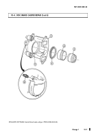
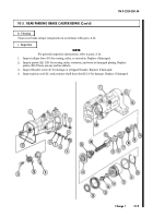
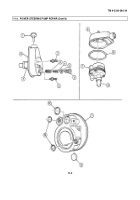
Remove parking brake spring (10) from parking brake lever (9) and caliper housing (1).
2.
Remove screw (11) and parking brake lever (9) from actuator shaft (12).
3.
Remove piston cap (26) from piston (22).
4.
Remove piston retaining screw (24) from piston (22).
5.
Turn piston (22) counterclockwise and remove from caliper housing (1).
6.
Remove piston boot (25) and piston seal (21) from caliper housing (1).
7.
Remove thrust screw retaining ring (20) and thrust screw spring shield (27) from caliper
housing (1).
8.
Remove thrust screw spring (28) and thrust screw (29) from caliper housing (1).
9.
Remove three actuator shaft bearings (19), bearing plate (18), and actuator shaft assembly
parts (17), (16), and (15) from caliper housing (1).
10.
Remove actuator dust seal (13) from caliper housing (1). Discard dust seal (13).
11.
Remove pin retaining plug assembly (5), antirotation pin spacer (6), and antirotation pin (7) from
caliper housing (1).
12.
Remove bleeder screw cap (3) and bleeder screw (2) from caliper housing (1).
13.
Remove O-rings (4) and (8) from retaining plug assembly (5) and antirotation pin (7). Remove
O-rings (23) and (14) from piston retaining screw (24) and actuator shaft (17). Discard O-rings (4), (8),
(23), and (14).
a. Disassembly
Back to Top

