TM-9-2320-280-34 - Page 690 of 1258
1 4 - 1 7 . AIR-CONDITIONING SYSTEM SERVICING (Cont'd)
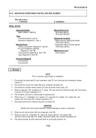
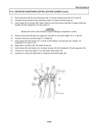
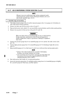
1.
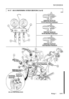
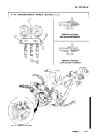
Turn high pressure gauge valve (2) and low pressure gauge valve (1) on gauge set (3) clockwise to
their front-seated (closed) positions.
2.
Remove two dust caps (9) from service valves (6) and (7).
3.
Ensure both service valve shafts (11) are moved fully counterclockwise until in back-seated position.
4.
Remove two cap nuts (8) from service valve ports (10) and (12).
________
WARNING
________
Make sure hand valves on manifold gauge set are in closed position
during connection, and hoses are clear of any moving parts in
engine compartment. Injury to personnel or damage to equipment
may result.
5.
Connect low pressure gauge hose (5) on manifold gauge set (3) to suction (low side) service valve
port (10).
6.
Connect high pressure gauge hose (4) on manifold gauge set (3) to discharge (high side) service
valve (6).
7.
Hang manifold gauge set (3) so that hoses (5) and (4) are well away from moving engine parts.
NO T E
• Service valve mid-seated position is used for discharging,
flushing, evacuating, charging, and testing.
• Do not perform step 9 if system is already evacuated. High and
low pressure hoses must be purged with FR-12 or R-12 for
charging purposes (refer to task f.)
8.
Turn both service valve shafts (11) to mid-seated position.
9.
Loosen low pressure gauge hose (5) and high pressure gauge hose (4) at manifold gauge set slightly
for a second to purge air from hoses, and then tighten.
a. Manifold Gauge Set Installation
NO T E
Whenever any air-conditioning vapor system component needs
replacement, the system must be discharged, flushed, and a new
dryer bottle installed (para. 14-19).
TM 9-2320-280-34
1 4 - 9 0
Change 1
Back to Top

