TM-9-2320-283-13-P - Page 27 of 400
0002-1
TM 9-2320-283-13&P
0002
OPERATOR AND FIELD MAINTENANCE
EQUIPMENT DESCRIPTION AND DATA
EQUIPMENT CHARACTERISTICS, CAPABILITIES, AND FEATURES
The ABS installed on the M915A1 tractor is provided to keep wheels from locking up during braking. ABS also
enables the operator to maintain steering control under heavy braking by preventing the tractor from skidding
sideways. In addition, the increased stability during braking resulting from ABS reduces the chances of a crash
and/or severity of impact in a crash.
ABS significantly improves safety and control for operators when braking in most on-road conditions and other
types of terrain. On high-traction surfaces such as concrete and asphalt, braking distances are minimized with
the ABS. However, in other types of terrain or conditions such as on gravel or in deep snow, ABS may increase
braking distances as a result of preventing wheel lock-up during braking. On very slippery surfaces such as sheet
ice, ABS may lose its effectiveness to prevent a skid because it becomes possible to lock multiple wheels at
once.
The ABS consists of four wheel speed sensors, four modulators, and an Electronic Control Unit (ECU) installed
on the existing brake circuit. The system performs a self-check automatically and warning indicator light alerts
operator to any malfunction should it occur. A test blink code switch allows the maintainer to troubleshoot ABS
without the use of hand-held or PC-based diagnostic tools. A diagnostic connector is also provided to enable the
use of remote diagnostic tools for troubleshooting.
LOCATION AND DESCRIPTION OF MAJOR COMPONENTS
This work package covers major components of the ABS.
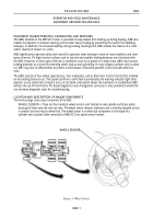
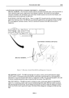
WHEEL SENSOR – There are four identical wheel sensors each located on axle spindle and brake spider
housings of front axle and rear-rear axle. The wheel sensor remains stationary and is initially adjusted so that
it contacts the tone ring on wheel hub. The wheel sensor is an electrical component in the shape of a
cylinder with a power cable connected to ABS ECU via speed sensor harness.
WHEEL SENSOR
Figure 1 Wheel Sensor.
Back to Top

