TM-9-2320-283-13-P - Page 33 of 400
0003-1/2 blank
INTRODUCTION
This work package is intended to provide the operator and maintainer with a basic understanding of design and
function of the M915A1 equipped with ABS. This information describes how the system works to enable the
operator and maintainer to better utilize the equipment.
FUNCTION OF ANTI-LOCK BRAKE SYSTEM (ABS)
The ABS is a brake system which prevents the wheels from locking while braking. The ABS works with the
vehicle’s regular brake system by automatically pulsing the brakes as if the operator were manually pumping the
brake pedal to prevent wheel lockup.
When operator applies the service brake pedal, the ABS applies and releases braking pressure at the wheels up to
20 times a second. The process is repeated continuously, and is the cause of the characteristic pulsing feel
through brake pedal.
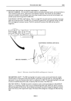
ABS is controlled by the ECU which monitors rotation speed of each wheel by way of a speed sensor. There are
a total of four speed sensors on the M915A1 truck; two on the front axle and two on the rear-rear axle. When the
service brake is applied, the ECU senses the speed of each wheel. If one or more wheels begin to rotate
considerably slower than the others (a condition that will bring on a lockup), the ECU will activate the
modulator(s) controlling the braking force at the slower rotating wheel(s) to decrease pressure on the breaking
circuit and reduce the braking force. The slower rotating wheel or wheels begin to turn faster and the braking
force is reapplied. This process is repeated continuously while brakes are applied. The ABS installed on the
M915A1 tractor does not include Automatic Traction Control (ATC).
STEERING AXLE CONTROL
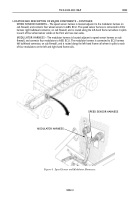
The front or steering axle contains a speed sensor and modulator on both wheels. When the service brakes are
applied, the ECU blends the braking force between the two steering axle brakes to help reduce steering wheel
pull on slippery road surfaces. This brake application control is called Modified Individual Regulation (MIR).
DUAL DRIVE AXLE CONTROL
The brakes on the forward-rear and rear-rear axles are controlled as a unit; one modulator controls both right-
side rear wheels and the other modulator controls both left-side rear wheels. The rear speed sensors are installed
on the rear-rear axle wheel ends only. When the service brakes are applied, the brakes on both forward-rear and
rear-rear axles receive equal braking pressure during a stop.
BLINK CODES
Blink codes enable the maintainer to troubleshoot ABS problems without using a hand-held or PC-based
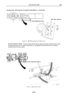
diagnostic tool. The ABS amber warning light, located in the cab on the center control panel, is designed to
display sequences of blinks communicated by the ABS ECU. The blink codes are activated by the test switch,
also located on the center control panel.
TM 9-2320-283-13&P
0003
OPERATOR AND FIELD MAINTENANCE
THEORY OF OPERATION
END OF WORK PACKAGE
Back to Top


