TM-9-2320-283-13-P - Page 37 of 400
0004-1
TM 9-2320-283-13&P
0004
OPERATOR AND FIELD MAINTENANCE
DESCRIPTION AND USE OF OPERATOR CONTROLS AND INDICATORS
This work package contains a description and illustration for each ABS control and indicator on the M915A1
equipped with ABS. It is important to learn the name, location, and function of all controls and indicators before
attempting to operate or perform maintenance on the tractor. Operators will know the location and understand
proper use of all controls and indicators before operating the tractor.
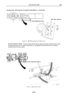
Table 1. Center Control Panel.
Key
Control/Indicator
Function
1
Center Control Panel
The center control panel is modified to contain the
ABS warning light and test switch. If necessary,
center control panel can be hinged open to access
ABS electrical harness wiring by turning two screws,
located at the top of the panel, 90 degrees in either
direction.
1
Figure 1. Center Control Panel.
Back to Top

