TM-9-2320-283-13-P - Page 38 of 400
TM 9-2320-283-13&P
0004
0004-2
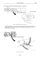
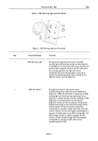
Table 2. ABS Warning Light and Test Switch.
Key
Control/Indicator
Function
1
ABS Warning Light
During normal operation of the tractor, the ABS
warning light will illuminate and go out when ignition
is switched on, and may illuminate and go out when the
service brake is applied. Should an actual malfunction
occur during operation, this light will remain
illuminated. The same warning light is also used to
indicate troubleshooting blink codes, initiated by the
ABS test switch, from the ABS ECU.
2
ABS Test Switch
The ABS test switch is only used to access
troubleshooting blink codes built into the ABS ECU
diagnostics. When the test switch is depressed the ABS
warning light will illuminate. By depressing the test
switch for a specific duration and then releasing it, ABS
diagnostics is activated (turned on) and several
diagnostic modes can then be accessed. Timed pauses
between depressing the test switch will change modes,
and the number of times the switch is depressed
corresponds to a specific trouble code mode. Once the
mode is selected, the ECU will begin responding with a
sequence of blink codes via the ABS warning light. The
total number of blinks is called a message, and the
number of blinks flashed through ABS warning light
corresponds to a specific trouble code used for
troubleshooting the ABS.
1
2
Figure 2. ABS Warning Light and Test Switch.
Back to Top

