TM-9-2320-283-13-P - Page 30 of 400
TM 9-2320-283-13&P
0002
0002-4
LOCATION AND DESCRIPTION OF MAJOR COMPONENTS – CONTINUED
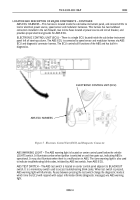
ABS ECU HARNESS – This harness is located inside the cab below instrument panel, and connects ECU to
tractor electrical power source, speed sensor and modulator harnesses. This harness has two bulkhead
connectors installed in the cab firewall, two in-line fuses located at power source and circuit breaker, and
provides proper electrical grounds for ABS ECU.
ELECTRONIC CONTROL UNIT (ECU) – There is a single ECU located inside the cab below instrument
panel left of steering column. The ABS ECU is connected to speed sensor and modulator harness via ABS
ECU and diagnostic connector harness. The ECU controls all functions of the ABS and has built-in
diagnostics.
ELECTRONIC CONTROL UNIT (ECU)
ABS ECU HARNESS
Figure 5. Electronic Control Unit (ECU) and Diagnostic Connector.
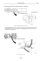
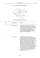
ABS WARNING LIGHT – The ABS warning light is located on center control panel below the vehicle
LIGHTS switch. It illuminates amber when ignition is switched on and then goes out, indicating ABS is
operational. It may also illuminate when there is a malfunction in ABS. The same warning light is also used
to indicate troubleshooting blink codes, initiated by ABS test switch, from ABS ECU.
ABS TEST SWITCH – The ABS test switch is located on center control panel adjacent to BLACKOUT
switch. It is a momentary switch used to access troubleshooting blink codes. When test switch is pressed,
ABS warning light will illuminate. Pauses between pressing the test switch change the diagnostic mode at
which time the ECU will respond with output information blinks (diagnostic messages) via ABS warning
light.
Back to Top

