TM-9-2320-328-13-P-1 - Page 517 of 1318
TM 9-2320-328-13&P-1
0063-41
DRAFT
0063
HWT2088
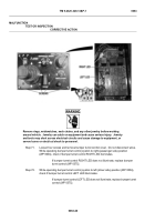
WARNING
ICON 3
Remove rings, wristwatches, neck chains, and any other jewelry before working
around vehicle.
Jewelry can catch on equipment and cause serious injury.
Jewelry
and tools may short across electrical circuits and cause damage to equipment, or
severe burns or electrical shock to personnel.
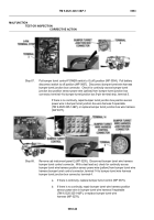
Step 62.
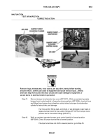
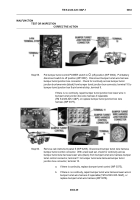
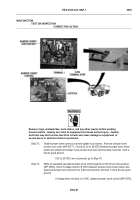
Put bumper turret control POWER switch to O (off) position (WP 0004).
Pull battery
disconnect switch to off position (WP 0007).
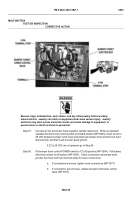
Remove bumper turret junction box cover
(WP 0377).
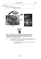
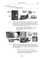
Check for continuity across bumper turret position sensor ground wire
(blue) from bumper turret junction box 9-pin terminal strip, terminal 5 to a known good
ground.
If there is no continuity, go to Step 69.
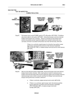
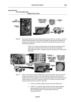
Step 63.
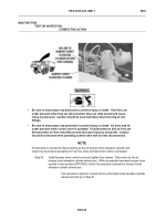
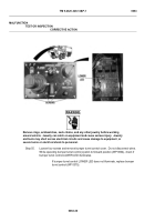
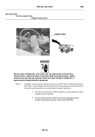
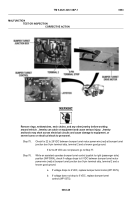
Push battery disconnect switch to on position (WP 0007).
Put bumper turret control
POWER switch to
|
(on) position.
Put OSCILLATION switch to
|
(on) position
(WP 0004).
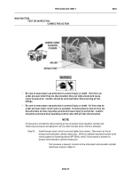
Set OSCILLATION LIMITS control knobs to maximum left and right limits
(WP 0004).
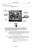
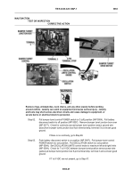
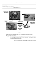
Check for 7 to 9 VDC between bumper turret position sensor power wire
(yellow) at bumper turret junction box 9-pin terminal strip, terminal 3 and a known good
ground.
If 7 to 9 VDC are not present, go to Step 67.
MALFUNCTION
TEST OR INSPECTION
CORRECTIVE ACTION
Back to Top

