TM-9-2320-328-13-P-1 - Page 526 of 1318
TM 9-2320-328-13&P-1
0063-50
DRAFT
0063
END OF TASK
HWT2095A
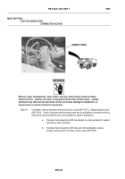
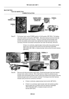
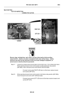
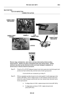
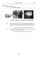
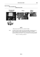
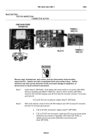
Step 79.
Put bumper turret control POWER switch to
(off) position (WP 0004).
Pull battery
disconnect switch to off position (WP 0007).
Disconnect bumper turret wire harness
bumper turret junction box connector.
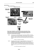
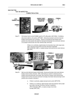
Check for continuity across bumper turret
junction box motor power wire (black) from bumper turret junction box connector,
terminal 1 to bumper turret junction box 9-pin terminal strip, terminal 1.
If there is no continuity, repair bumper turret junction box motor power wire
(black) in bumper turret junction box wire harness if repairable
(TM 9-2320-325-14&P), or replace bumper turret junction box wire harness
(WP 0377).
HWT2095
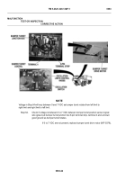
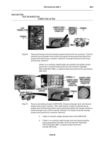
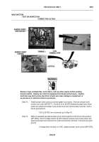
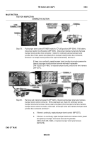
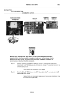
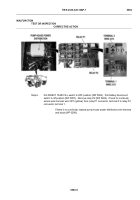
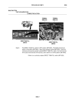
Step 80.
Remove cab instrument panel E (WP 0205).
Disconnect bumper turret wire harness
bumper turret control connector.
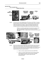
With a test lead set, check for continuity across
bumper turret wire harness motor power wire (black) from bumper turret wire harness
bumper turret control connector, terminal 4 to bumper turret wire harness bumper turret
junction box connector, terminal 1.
a.
If there is continuity, replace bumper turret control (WP 0375).
b.
If there is no continuity, repair bumper turret wire harness motor power
wire (black) in bumper turret wire harness if repairable
(TM 9-2320-325-14&P), or replace bumper turret wire harness
(WP 0278).
MALFUNCTION
TEST OR INSPECTION
CORRECTIVE ACTION
Back to Top

