TM-9-2320-328-13-P-2 - Page 1045 of 1390
TM 9-2320-328-13&P-2
0281-5
DRAFT
0281
INSTALLATION
NOTE
•
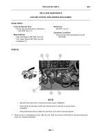
Route cab pump control wire harness as noted prior to removal.
•
Install cable ties, split loom, and cushion clips as required.
1.
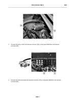
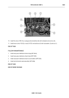
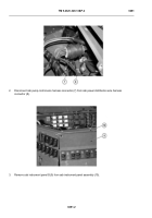
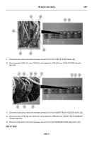
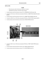
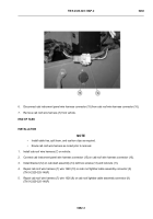
Connect cab pump control wire harness connector (37) on WINDSHIELD DELUGE switch (38).
2.
Connect wire 2772 (33), wire 1023 (34), and jumperwire 2768 (35) on UNDER TRUCK NOZZLES indicator
light (36).
3.
Connect cab pump control wire harness connector (31) on UNDER TRUCK NOZZLES switch (32).
4.
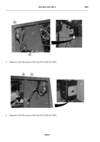
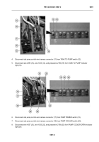
Connect wire 2830 (27), wire 1023 (28), and jumperwire 2768 (29) on FOAM SYSTEM indicator light (30).
5.
Connect cab pump control wire harness connector (25) on FOAM SYSTEM switch (26).
-
-
-
-
-
-
-
-
-
-
-
-
-
-
-
-
-
-
-
-
-
-
-
-
-
-
-
-
-
-
-
-
-
-
-
-
-
6.
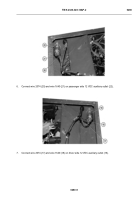
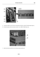
Connect wire 4037 (21), wire 1023 (22), and jumperwire 2768 (23) on PUMP COOLER OPEN indicator
light (24).
7.
Connect cab pump control wire harness connector (19) on PUMP COOLER switch (20).
8.
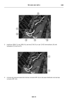
Connect cab pump control wire harness connector (17) on PUMP PRIMER switch (18).
HWT2166
Back to Top

