TM-9-2320-328-13-P-3 - Page 67 of 844
TM 9-2320-328-13&P-3
0335-1
DRAFT
0335
Change 1
FIELD LEVEL MAINTENANCE
LIGHT BEZEL COVER(S) REPLACEMENT
INITIAL SETUP:
DRIVER SIDE LIGHT BEZEL COVER REMOVAL
NOTE
Both driver side light bezel covers are removed the same way.
Front driver side light bezel
cover shown.
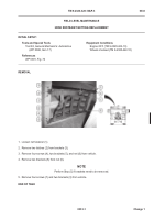
Remove eight screws (1), lockwashers (2), washer (3), and light bezel cover (4) from light bezel (5).
Discard
lockwashers.
END OF TASK
DRIVER SIDE LIGHT BEZEL COVER INSTALLATION
NOTE
Both driver side light bezel covers are installed the same way.
Front driver side light bezel
cover shown.
Install light bezel cover (4) on light bezel (5) with eight washers (3), lockwashers (2), and screws (1).
END OF TASK
-
-
-
-
-
-
-
-
-
-
-
-
-
-
-
-
-
-
-
-
-
-
-
-
-
-
-
-
-
-
-
-
-
-
-
-
-
.
.
.
.
.
.
.
.
.
.
.
.
.
.
.
.
.
.
.
.
.
.
.
.
.
.
.
.
HWT3393
Tools and Special Tools
Tool Kit, General Mechanic’s: Automotive
(WP 0398, Item 17)
Materials/Parts
Lockwasher (8)
Lockwasher (10)
References
WP 0391, Fig. 29
Equipment Conditions
Engine OFF (TM 9-2320-422-10)
Wheels chocked (TM 9-2320-422-10)
Back to Top


