TM-9-2320-341-10 - Page 269 of 962
NOTE
•
If lockout assembly is oriented correctly (refer to table 1), skip to Step
(4).
•
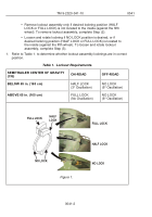
Remove lockout assembly only if desired lockring position (HALF
LOCK or FULL LOCK) is not located to the inside (against the fifth
wheel).
•
To remove lockout assembly, complete Step (2).
•
Loosen and rotate lockring if NO LOCK position is desired, or if
desired lockring position (HALF LOCK or FULL LOCK) is located to
the inside (against the fifth wheel).
•
To loosen and rotate lockout assembly, skip to Step (3).
•
Both fifth wheel lockout assemblies are removed the same way
(driver side shown).
2.
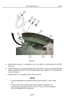
Remove fifth wheel lockout assembly and orient correctly:
TM 9-2320-341-10
0041
0041-3
Back to Top

