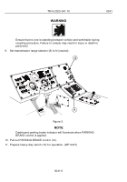
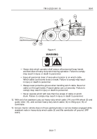
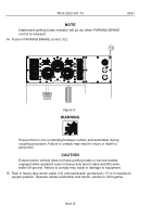
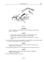
TM-9-2320-341-10 - Page 270 of 962
6
5
8
7
2
3
4
4
9
10
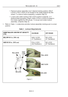
1
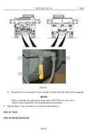
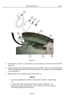
Figure 2.
a.
Remove four screws (1), lockwashers (2), cover plate (3), and lockring (4) from fifth
wheel (5).
b.
Install lockring (4) so desired surface area (see Table 1 above) is oriented directly
under engagement area (6) of fifth wheel (5) with cover plate (3), four lockwashers
(2) and screws (1).
c.
Repeat Step (2) for opposite side of fifth wheel (5).
NOTE
•
If lockout assembly is oriented correctly (refer to table 1), skip to Step
(4).
•
Loosen and rotate lockring if NO LOCK position is desired, or if
desired lockring position (HALF LOCK or FULL LOCK) is located to
the inside (against the fifth wheel).
TM 9-2320-341-10
0041
0041-4
Back to Top

