TM-9-2320-341-10 - Page 271 of 962
•
Both fifth wheel lockout assemblies are rotated the same way (driver
side shown).
3.
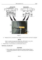
Rotate fifth wheel lockout assembly:
a.
Loosen four screws (1).
NOTE
•
Driver side lockring rotates toward the rear of vehicle.
•
Passenger side lockring rotates toward the front of vehicle.
b.
Rotate lockring (4) so desired surface area (see table 1 above) is oriented directly
under engagement area (6) of fifth wheel (5).
c.
Tighten four screws (1).
d.
Repeat Step (3) for opposite side of fifth wheel (5).
NOTE
Fifth wheel has two lock release handles.
4.
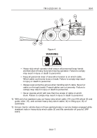
Pull fifth wheel secondary lock release handle (7) completely out as far as it will go.
5.
Pull out fifth wheel primary lock release handle (8) and hook it in out position.
6.
Push down rear of fifth wheel (5) until it rests on stop (9) below guide ramps (10).
CAUTION
•
Ensure there is a generous amount of grease on fifth wheel, ramps,
kingpin, and steering wedge. Failure to comply may result in damage
to equipment.
•
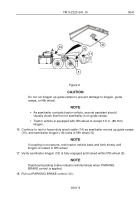
Tractor vehicle and semitrailer coupling should be performed with the
tractor vehicle and semitrailer in a straight line. If wedge of trailer is
not aligned with tractor vehicle fifth wheel, adjust either tractor
vehicle, trailer, or both to align them. Failure to comply may result in
damage to equipment.
7.
Prepare semitrailer for coupling (refer to TM 5-2330-378-14&P). (WP 0146)
8.
Slowly back tractor vehicle (WP 0051) to within 3 ft. (.92 m) of semitrailer. Stop tractor
vehicle.
TM 9-2320-341-10
0041
0041-5
Back to Top

