TM-9-2320-341-10 - Page 314 of 962
•
Lockouts must be positioned as identified in Table 1. Failure to
comply may result in damage to equipment.
NOTE
•
This procedure is a two soldier task.
•
Leave tractor vehicle running during procedure for heavy-duty winch
operation.
•
Tractor vehicle is equipped with fifth wheel to accept 3.5 in. (89 mm)
kingpin.
•
If fifth wheel lockout assemblies are not positioned correctly,
complete Step (2) or (3) as applicable.
•
Remove lockout assembly only if desired lockring position (HALF
LOCK or FULL LOCK) is not located to the inside (against the fifth
wheel). To remove lockout assembly, complete Step (2).
•
Loosen and rotate lockring if NO LOCK position is desired, or if
desired lockring position (HALF LOCK or FULL LOCK) is located to
the inside (against the fifth wheel). To loosen and rotate lockout
assembly, complete Step (3).
1.
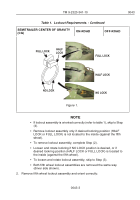
Refer to Table 1. to determine whether lockout assembly lockrings are in correct
position.
Table 1.
Lockout Requirements.
SEMITRAILER CENTER OF GRAVITY
(CG)
ON-ROAD
OFF-ROAD
BELOW 65 in. (165 cm)
HALF LOCK
(3° Oscillation)
NO LOCK
(6° Oscillation)
ABOVE 65 in. (165 cm)
FULL LOCK
(No Oscillation)
NO LOCK
(6° Oscillation)
TM 9-2320-341-10
0043
0043-2
Back to Top

