TM-9-2320-341-10 - Page 510 of 962
9
7
10
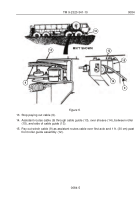
M977 SHOWN
Figure 4.
11. Move winch shift lever (4) to OUT and pay out winch cable (9), while assistant routes
cable (9) through notch in fender (11).
NOTE
•
Do not place cable between tensioning device pulleys at this time.
•
When pulling cable through tensioning device, push sheave towards
frame rail to allow clevis to pass through.
12. Pay out cable (9) while assistant pulls cable (9) until it is 6 in. to 1 ft. (15 cm to 30 cm)
past the front roller guide (12).
TM 9-2320-341-10
0084
0084-4
Back to Top


