TM-9-2320-361-20 - Page 307 of 1207
TM 9-2320-361-20
3-3. ENGINE REAR MOUNT PAD REPLACEMENT
This task covers:
a. Removal
b. Installation
INITIAL SETUP:
APPLICABLE MODELS
EQUIPMENT CONDITION
All
Parking brake set (TM 9-2320-361-10).
MATERIALS/PARTS
GENERAL SAFETY INSTRUCTIONS
Locknut
Do not put fingers between frame and engine
REFERENCES (TM)
support.
TM 9-2320-361-10
TM 9-2320-361-20P
a. Removal
NOTE
Perform step 1 for engine left rear mount.
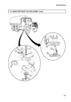
1. Remove nut (1) and accelerator linkage (3) from throttle control lever (2).
NOTE
Right and left engine rear mounts are removed the same way. This
procedure covers the right engine rear mount.
2. Remove locknut (10), washer (9), and lower rear engine pad (8) from frame (7). Discard locknut (10).
3. Position hydraulic jack (13) and wood blocks (14) under transmission (12) lifting point. Raise
transmission (12) just enough to take weight off upper rear engine pad (11).
WARNING
Do not put fingers between frame and engine support. Jack failure
may cause injury to personnel.
4. Remove screw (4), washer (5), and upper rear engine pad (11) from frame (7) and engine support (6).
1. Install upper rear engine pad (11) on frame (7) with washer (5) and screw (4).
2. Lower hydraulic jack (13) and remove jack (13) and wood blocks (14) from transmission (12).
3. Install lower rear engine pad (8) on frame (7) with washer (9) and new locknut (10). Tighten
locknut (10) 65-70 lb-ft (88-95 N·m).
NOTE
Perform step 4 for engine left rear mount.
4. Install accelerator linkage (3) on throttle control lever (2) with nut (1).
3-4
Back to Top

