TM-9-2320-361-20 - Page 549 of 1207
TM 9-2320-361-20
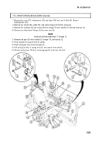
7-13. FRONT SPRING REPLACEMENT (Contd)
1.
2.
3.
4.
5.
6.
7.
8.
9.
10.
11.
12.
13.
14.
15.
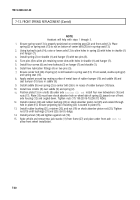
NOTE
Assistant will help with steps 1 through 5.
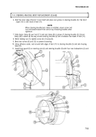
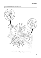
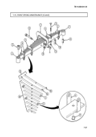
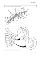
Ensure spring seat (13) is properly positioned on centering peg (22) and front axle (12). Place
spring (2) on spring seat (13) so nut on bottom of center bolt (26) is in spring seat (13).
Using hydraulic jack (14), raise or lower axle (12) to aline holes in spring (2) with holes in shackle (1)
and hanger (7).
Install spring (2) on shackle (1) and hanger (7) with two pins (5).
Turn pins (5) to aline pin retaining screw slots with holes in shackle (1) and hanger (7).
Install four screws (6) and new locknuts (3) on hanger (7) and shackle (1).
Install two lubrication fittings (4) on two pins (5).
Ensure center bolt (26) of spring (2) is still seated in spring seat (13). If not seated, realine spring (2)
and spring seat (13).
Apply sealant around top mating surface of metal base of rubber bumper (10) and saddle (9) and
seat bumper (10) base in saddle (9).
Install saddle (9) over spring (2) so center bolt (26) is in recess of rubber bumper (10) base.
Install two U-bolts (8) over saddle (9) and spring (2).
Position plate (15) on u-bolts (8) under axle
housing (12) and
install four new lockwashers (16) and
nuts (17). Plate (15) must have shock absorber hole on wheel side of spring (2) toward rear of front
axle housing (12) and angled down. Tighten nuts (17) 190-230 lb-ft (258-312 NŽm).
Install retainer (24) and rubber bushing (23) on shock absorber piston rod (25) and extend through
hole in plate (15). Ensure projecting lip of bushing (23) is seated in plate (15).
Install rubber bushing (21), retainer (20), and nut (19) on shock absorber piston rod (25). Tighten
nut (19) until bushings (21) and (23) start to bulge.
Install jamnut (18) and tighten against nut (19).
Raise vehicle and remove two jack stands (11) from frame (27) and place under front axle
(12) to
allow front wheel installation.
7-30
Back to Top

