TM-9-2320-361-20 - Page 595 of 1207
TM 9-2320-361-20
8-8. SERVICE BRAKE ADJUSTMENT
This task covers:
Service Brake Adjustment
INITIAL SETUP:
APPLICABLE MODELS
EQUIPMENT CONDITION
All
Parking brake set (TM 9-2320-361-10).
MATERIALS/PARTS
Front or rear wheels removed (para. 9-2).
Adjust wheel bearing (para. 9-5).
Lockwasher
REFERENCES [TM]
TM 9-2320-361-10
TM 9-2320-361-20P
NOTE
The adjustment procedure for front and rear brakes is done the
same way. This procedure covers the front brakes.
Allow brakes to cool before adjusting.
Service Brake Adjustment
1.
2.
3.
4.
5.
6.
7.
8.
9.
10.
11.
12.
13.
14.
15.
8-22
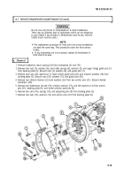
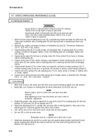
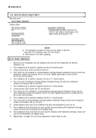
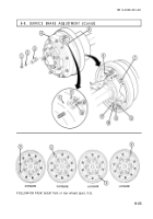
Remove nut (1), lockwasher (2), and inspection slot cover (3) from brakedrum (4). Discard
lockwasher (2).
Turn brakedrum (4) to position inspection slot (5) at 8 o’clock location.
Loosen jamnut (8) on anchor pin (9) one full turn.
Turn anchor pin (9) clockwise or counterclockwise until gap between brakeshoe lining (13) and inner
brakedrum surface (12) measures .010 in. (.25 mm). Tighten jamnut (8) on anchor pin (9)
80-110 lb-ft (109-149 NŽm).
Turn brakedrum (4) to position inspection slot (5) at 11 o’clock location.
Turn cam stud (7) clockwise until gap between brakeshoe lining (13) and inner brakedrum
surface (12) measures .020 in. (.50 mm).
Turn brakedrum (4) to position inspection slot (5) at 5 o’clock location.
Loosen jamnut (10) on anchor pin (11) one full turn.
Turn anchor pin (11) clockwise or counterclockwise until gap between brakeshoe lining (13) and
inner brakedrum surface (12) measures .010 in. (.25 mm). Tighten jamnut (10) on anchor pin (11)
80-110 lb-ft (109-149 NŽm).
Turn brakedrum (4) to position inspection slot (5) at 1 o’clock location.
Turn cam stud (6) counterclockwise until gap between brakeshoe lining (13) and inner brakedrum
surface (12) measures .020 in. (.50 mm).
Install inspection slot cover (3) on brakedrum (4) with new lockwasher (2) and nut (1).
Turn brakedrum (4) by hand and turn cam stud (6) counterclockwise until brakedrum (4) drags.
Loosen cam stud (6) until brakedrum (4) slightly drags.
Turn brakedrum (4) by hand and turn cam stud (7) clockwise until brakedrum (4) drags. Loosen cam
stud (7) until brakedrum (4) slightly drags.
Repeat steps 1 through 14 to do service adjustment of other wheel on axle.
Back to Top

