TM-9-2320-361-20 - Page 613 of 1207
TM 9-2320-361-20
8-15. HYDRAULIC BRAKE LINE REPLACEMENT
This task covers
INITIAL SETUP:
APPLICABLE MODELS
REFERENCES (TM)
All
LO 9-2320-209-12-1
MATERIALS/PARTS
TM 9-2320-361-10
TM 9-2320-361-20P
Lockwasher
Locknut
EQUIPMENT CONDITION
Two screw-assembled lockwashers
Parking brake set (TM 9-2320-361-10).
Cap and plug set (Appendix C, Item 8)
GENERAL SAFETY INSTRUCTIONS
New, longer hydraulic brake line must be installed.
WARNING
Short front flexible hydraulic brake lines are subject to failure during
full steering travel and must be replaced with new, longer flexible
hydraulic brake lines P/N 7409330. Failure to do this may cause
injury or death to personnel. Refer to para. 8-16 for replacement.
CAUTION
Cap or plug all openings immediately after disconnecting lines and
hoses to prevent contamination. Failure to do so may result in
internal parts damage.
NOTE
All hydraulic brake and compressed air lines are replaced the same.
This procedure covers the front flexible hydraulic brake line.
a. Removal
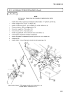
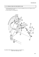
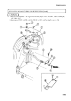
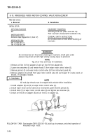
1. Disconnect spring (7) from spring plate (5).
2. Remove nut (3), lockwasher (4), and spring plate (5) from steering arm (2). Discard lockwasher (4).
3. Remove locknut (14), screw (6), spring (7), and clamp (8) from flexible hydraulic brake line (15).
Discard locknut (14).
NOTE
Have container ready to catch hydraulic fluid.
4. Disconnect flexible hydraulic brake line (15) from inlet connector (1).
5. Remove brake line (13) from flexible hydraulic brake line (15).
6. Remove nut (12) and flexible hydraulic brake line (15) from bracket (10).
7. Remove two screw-assembled lockwashers (9) and bracket (10) from axle housing (11) and
brake line (13). Discard screw-assembled lockwashers (9).
b. Installation
1. Install bracket (10) on axle housing (11) with two new screw-assembled lockwashers (9).
2. Connect flexible hydraulic brake line (15) to inlet connector (1).
3. Install flexible hydraulic brake line (15) on bracket (10) with nut (12).
4. Install brake line (13) on flexible hydraulic brake line (15).
5. Install clamp (8) on flexible hydraulic brake line (15) with spring (7), screw (6), and new locknut (14).
8-40
Back to Top

