TM-9-2320-361-20 - Page 623 of 1207
TM 9-2320-361-20
8-22. AIRBRAKE VALVE REPLACEMENT
This task covers:
a.
Removal
b.
Installation
INITIAL SETUP:
APPLICABLE MODELS
EQUIPMENT CONDITION
M275A2
Parking brake set (TM 9-2320-361-10).
MATERIALS/PARTS
Air reservoirs drained (TM 9-2320-361-10).
Two drivescrews
GENERAL SAFETY INSTRUCTIONS
Antiseize
tape (Appendix C, Item 27)
Do not disconnect air lines before draining air
REFERENCES (TM)
TM 9-2320-361-10
reservoirs.
TM 9-2320-361-20P
a. Removal
WARNING
Do not disconnect air lines before draining air reservoirs. Small
parts under pressure may shoot out with high velocity, causing
injury to personnel.
1.
2.
3.
4.
5.
NOTE
The left and right side valves are replaced the same. This procedure
covers the left side.
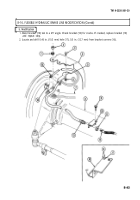
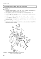
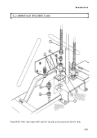
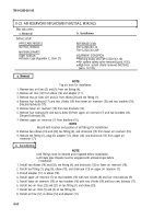
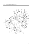
Remove air hose (1) from adapter (8).
Remove adapter (8) from airbrake valve (2) and inspect adapter (8) for stripped threads, cracks, or
breaks. If damaged, replace.
Remove
air line (5) from adapter (6).
Remove adapter (6) and airbrake valve (2) from bracket (4) and plate
(3).
Inspect adapter
(6)
for
stripped threads, cracks, or breaks, If damaged, replace.
NOTE
Perform step 5 only if plate requires replacement.
Remove two drivescrews (7) and plate (3) from bracket (4). Discard drivescrews (7).
b. Installation
NOTE
Perform step 1 only if plate was removed.
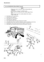
1. Install plate (3) on bracket (4) with two new drivescrews (7).
NOTE
All male pipe threads must be wrapped with antiseize tape before
installation.
2. Install airbrake valve (2) on bracket (4) with adapter (6).
3. Install air line (5) on adapter (6).
4. Install adapter (8) on airbrake valve (2).
5. Install air hose (1) on adapter (8).
8-50
Back to Top

