TM-9-2320-361-20 - Page 635 of 1207
TM 9-2320-361-20
8-26. AIR COMPRESSOR AND PULLEY REPLACEMENT
This task covers:
a. Removal
c. Assembly
b. Disassembly
d. Installation
INITIAL SETUP:
APPLICABLE MODELS
All
MATERIALS/PARTS
Three gaskets
Eight lockwashers
Antiseize tape (Appendix C, Item 27)
Cap and plug set (Appendix C, Item 8)
REFERENCES (TM)
TM 9-2320-361-10
TM 9-2320-361-20P
EQUIPMENT CONDITION
Air reservoir drained (TM 9-2320-361-10).
Air compressor drivebelt removed (para. 8-28).
GENERAL SAFETY INSTRUCTIONS
Do not disconnect air lines before draining air
reservoirs.
Allow air compressor to cool before handling.
a. Removal
1.
2.
3.
4.
5.
6.
7.
8.
9.
WARNIN G
Do not disconnect air lines before draining air reservoirs. Small
parts under pressure may shoot out with high velocity, causing
injury to personnel.
Air compressor becomes hot during operation. Allow compressor
to cool before handling, or injury to personnel may result.
NOTE
Plug air lines as they are disconnected.
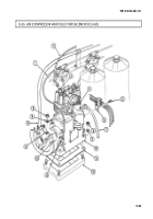
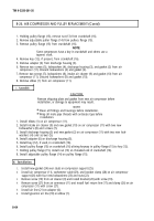
Remove air line (7) from adapter (4).
NOTE
On some air compressors, the air governor air line is on front of
compressor near pulley.
Remove air governor air line (2) from elbow (3).
Remove screw (14), clamp (13), and fuel pump return line (1) from air compressor (10). Tie fuel
pump return line (1) out of way.
Install screw (14) in air compressor (10).
Remove screw (5) and bracket (6) from air compressor (10).
Install screw (5) in air compressor (10).
Remove four nuts (8), lockwashers (9), and bracket (15) from base of air compressor (10). Discard
lockwashers (9).
Tie tachometer cable (16) and bracket (15) out of way.
Remove air compressor (10) and gasket (11) from air compressor support (12). Discard gasket (11).
8-62
Back to Top

