TM-9-2320-361-20 - Page 643 of 1207
TM 9-2320-361-20
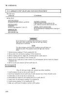
8-29. AIR COMPRESSOR GOVERNOR MAINTENANCE
This task covers:
a. Removal
c. Check and Adjustment
b. Installation
INITIAL SETUP:
APPLICABLE MODELS
EQUIPMENT CONDITION
All
Parking brake set (TM 9-2320-361-10).
SPECIAL TOOLS
Hood raised and secured (TM 9-2320-361-10).
Air reservoirs drained (TM 9-2320-361-10).
Gage pressure dial indicating
NSN 6685-00-387-9654
GENERAL SAFETY INSTRUCTIONS
MATERlALS/PARTS
Do not disconnect air lines before draining air
reservoirs.
Two screws
Antiseize tape (Appendix C, Item 27)
REFERENCES (TM)
TM 9-2320-361-10
TM 9-2320-361-20P
a. Removal
WARNING
Do not disconnect air lines before draining air reservoirs. Small
parts under pressure may shoot out with high velocity, causing
injury to personnel.
NOTE
Tag all air lines and hoses for installation.
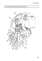
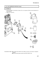
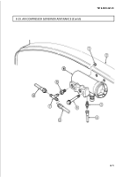
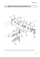
1. Remove two air lines (6) and (8) from tee fitting (7).
2. Remove air line (4) from adapter (3)
3. Remove two screws (5) and air compressor governor (10) from firewall (2). Discard screws (5).
4. Remove tee fitting (7), adapter (9), and adapter (3) from air compressor governor (10).
NOTE
Step 5 applies to M275A2 vehicles only.
5. Remove plug (1) from air compressor governor (10).
b. Installation
NOTE
Wrap all male pipe threads with antiseize tape before installation.
Step 1 applies to M275A2 vehicles.
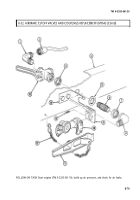
1. Install plug (1) in port F of air compressor governor (10).
2. Install adapter (3) and adapter (9) on air compressor governor (10).
3. Install tee fitting (7) on adapter (9).
4. Install air compressor governor (10) on firewall (2) with two new screws (5).
5. Install air line (4) on adapter (3).
6. Install two air lines (8) and (6) on tee fitting (7).
8-70
Back to Top

