TM-9-2320-361-20 - Page 649 of 1207
TM 9-2320-361-20
8-31. AIRBRAKE CUTOFF VALVES AND COUPLINGS REPLACEMENT
This task covers:
a. Removal
b. Installation
INITIAL SETUP:
APPLICABLE MODELS
All (except M275A2, M342A2, and M764)
EQUIPMENT CONDITION
MATERIALS/PARTS
Parking brake set (TM 9-2320-361-10).
Air reservoirs drained (TM 9-2320-361-10).
Lockwasher
Antiseize tape (Appendix C, Item 27)
GENERAL SAFETY INSTRUCTIONS
Do not disconnect air couplings before draining air
REFERENCES (TM)
reservoirs.
TM 9-2320-361-10
TM 9-2320-361-20P
WARNING
Do not disconnect air couplings before draining air reservoirs.
Small parts under pressure may shoot out with high velocity,
causing injury to personnel.
NOTE
The right emergency and left service couplings and cutoff valves are
replaced the same. This procedure covers the right side of service
brake.
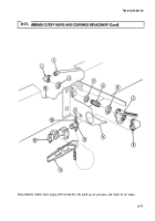
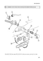
1. Remove dummy coupling (11) from coupling half (12).
2. Remove chain (13) and dummy coupling (11) from bracket (9).
3. Remove coupling half (12), nipple (10), and elbow (8) from cutoff valve (7).
4. Remove airline (2) and elbow (1) from connector (5).
5. Remove nut (3), cutoff valve (7) with connector (5), and lockwasher (4) from frame (14). Discard
lockwasher (4).
6. Remove nut (6) and connector (5) from cutoff valve (7).
b.
Installation
NOTE
Wrap all male pipe threads with antiseize tape before installation.
1. Install connector (5) and nut (6) on cutoff valve (7).
2. Install new lockwasher (4) and cutoff valve (7) with connector (5) on frame (14) with nut (3).
3. Install elbow (1) and air line (2) on connector (5).
4. Install elbow (8), nipple (10), and coupling half (12) on cutoff valve (7).
5. Install chain (13) and dummy coupling (11) on bracket (9).
6. Install dummy coupling (11) on coupling half (12).
7. Make sure cutoff valve (7) handle is turned to OFF position.
8-76
Back to Top

