TM-9-2320-361-24-1 - Page 255 of 1176
TM 9-2320-361-24-1
0014 00
0014 00-19/20 blank
INDICATORS, GAUGES, AND WARNING SYSTEM TROUBLESHOOTING (Contd)
MALFUNCTION
TEST OR INSPECTION
CORRECTIVE ACTION
10. HORN DOES NOT
OPERATE (Contd)
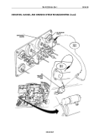
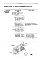
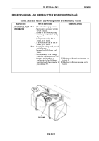
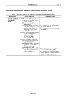
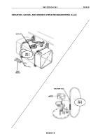
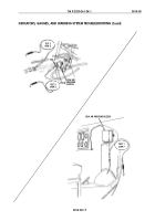
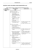
Test 4. Test horn switch continuity.
1. Disconnect lead 25 from air
horn solenoid to protect
multimeter.
2. Reinstall horn button cap,
spring, and contact
(WP 0113 00).
3. Set multimeter to RX 1 scale.
4. Connect negative lead to a
good frame ground.
5. Touch positive lead to lead 25
and press down until contact
touches base plate.
1. If continuity is present, reconnect
lead 25 and recheck horn operation.
2. If continuity is not present, remove
horn button and clean or replace
horn button (WP 0113 00).
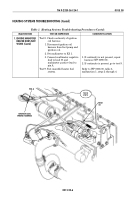
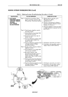
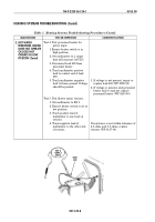
Table 1. Indicator, Gauges, and Warning System Troubleshooting (Contd).
TEST 2
STEP 4
TEST 2
STEP 3
HORN SOLENOID
PIN A
PIN B
25
25
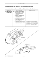
TEST 4
STEP 5
TEST 3
STEP 4
TEST 1
STEP 5
25
LEAD 25
END OF WORK PACKAGE
Back to Top

