TM-9-2320-361-24-1 - Page 514 of 1176
TM 9-2320-361-24-1
0046 00
0046 00-14
ENGINE REPLACEMENT (Contd)
INSTALLATION (Contd)
5.
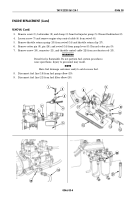
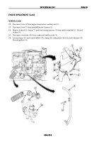
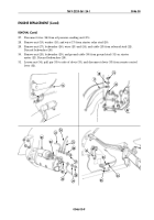
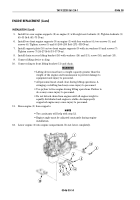
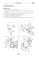
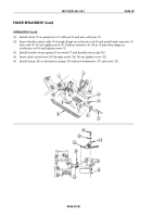
Install two rear engine supports (2) on engine (1) with eight new locknuts (3). Tighten locknuts (3)
45–55 lb-ft (61–75 N
•
m).
6.
Install two front engine supports (9) on engine (1) with four washers (4), two screws (5), and
screws (6). Tighten screws (5) and (6) 200–250 lb-ft (271–339 N
•
m).
7.
Install support plate (10) on two front engine supports (9) with six washers (8) and screws (7).
Tighten screws (7) 24–27 lb-ft (33–37 N
•
m).
8.
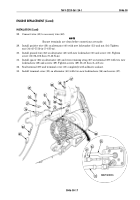
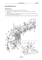
Install chain on rear lifting bracket (16) with washers (14) and (13), screw (16), and nut (15).
9.
Connect lifting device to sling.
10.
Connect sling to front lifting bracket (11) and chain.
WARNING
• Lifting device must have a weight capacity greater than the
weight of the engine and transmission to prevent damage to
equipment and injury to personnel.
• All personnel must stand clear during lifting operations. A
swinging or shifting load may cause injury to personnel.
• Use prybar to free engine during lifting operations. Failure to
do so may cause injury to personnel.
• Do not detach chain from engine until all engine weight is
equally distributed and engine is stable. An improperly
supported engine may cause injury to personnel.
11.
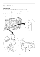
Raise engine (1) from supports.
NOTE
• Two assistants will help with step 12.
• Engine angle must be adjusted constantly during engine
installation.
12.
Lower engine (1) into engine compartment. Do not lower completely.
3
2
1
4
5
6
4
7
8
9
10
Back to Top

