TM-9-2320-361-34 - Page 223 of 764
TM 9-2320-361-34
I
10-4.
DIFFERENTIAL CARRIER REPAIR
THIS TASK COVERS:
a. Disassembly
c. Assembly and Adjustment
b. Cleaning and Inspection
INITIAL SETUP
APPLICABLE MODELS
All
SPECIAL TOOLS
Handle (Appendix B, Item 23)
Oil seal replacer (Appendix B, Item 25)
Oil seal remover (Appendix B, Item 28)
Bearing sleeve remover/replacer
(Appendix B, Item 24)
Bearing replacer (Appendix B, Item 26)
Two puller screws (Appendix B, Item 29)
Screw (Appendix B, Item 27)
TOOLS
General mechanic’s tool kit
(Appendix B, Item 1)
Mechanical puller kit (Appendix B, Item 23)
Torque wrench, 1./2-in. dr. (Appendix B, Item 7)
Torque wrench, 3/4-in. dr. (Appendix B, Item 6)
Dial indicator (Appendix B, Item 21)
Inside caliper micrometer
(Appendix B, Item 16)
Outside caliper micrometer
(Appendix B, Item 17)
Gage, force, mechanical
(Appendix B, Item 53)
Arbor press
Vise
MATERIALS/PARTS
Eight lockwashers (Appendix F, Item 125)
Six lockwashers (Appendix F, Item 138)
Two cotter pins (Appendix F, Item 13)
Two oil seals (Appendix F, Item 240)
Gasket and shim set (Appendix F, Item 84)
Woodruff
key (Appendix F, Item 297)
Blue pigment (Appendix C, Item 14)
Lubricating oil GO 80/90 (Appendix C, Item 11)
GAA grease (Appendix C, Item 8)
Sealing compound (Appendix C, Item 19)
Safety wire (Appendix C, Item 30)
PERSONNEL REQUIRED
Two
REFERENCES (TM)
TM 9-214
TM 9-2320-361-34P
EQUIPMENT CONDITION
Differential carrier removed (para. 10-3).
a.
Disassembly
CAUTION
1 .
2.
3.
4.
Scribe or center punch different marks on each side of carrier for
easy identification. Improper installation will result in damage to
parts.
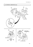
Scribe or center punch alinement marks on bearing caps (1) and carrier (17).
Remove two safety wires (5), two screws (3), and adjusting nut locks (2) from bearing caps (1).
Discard safety wires (5).
Remove four screws (4), washers (6), and two bearing caps (1) from carrier (17).
CAUTION
Scribe or center punch different marks on case halves and helical
drive gear. Marks should match those placed on bearing caps.
Improper installation will result in damage to equipment.
Scribe or center punch alinement marks on case halves (12) and (22) and helical drive gear (19).
10-6
Back to Top


