TM-9-2320-361-34 - Page 343 of 764
TM 9-2320-361-34
15-9.
TANK BODIES FRAME SILL MAINTENANCE
THIS
TASK COVERS:
a. Removal
c.
Installation
b. Inspection
INITIAL SETUP
APPLICABLE MODELS
M49A2C, M50A2, and M50A3
REFERENCES (TM)
TM 9-2320-361-34P
TOOLS
EQUIPMENT CONDITION
General mechanic’s tool kit
(Appendix B, Item 1)
Tank body removed (para. 15-8).
Breaker bar, 1/2-in. dr. (Appendix B, Item 15)
GENERAL SAFETY INSTRUCTIONS
1-1/8-in. socket, 1/2-in. dr. (Appendix B, Item 10)
●
Use care when working under tank body.
1-1./4-in. socket, 1/2-in. dr. (Appendix B, Item 19)
●
Ensure
lifting
capacity
is
greater
than weight of
Torque wrench, 1/2-in. dr. (Appendix B, Item 7)
tank body.
MATERIALS/PARTS
Two
locknuts (M49A2C and M50A3)
(Appendix F, Item 89)
Three locknuts (M50A2) (Appendix F, Item 89)
WARNING
●
Be careful when working under tank body placed on supports.
Tank body may fall causing injury to personnel.
●
Ensure lifting capacity is greater than weight of tank body.
Failure to do so may cause injury to personnel.
a. Removal
NOTE
●
Perform
steps
1
through
3
for M50A2 sill removal.
●
Perform
step
4
for
M49A2C sill removal.
●
Perform
steps
5
and
6
for
M50A3
sill removal.
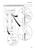
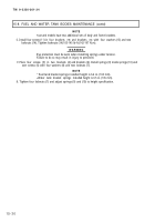
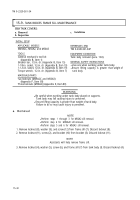
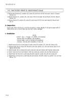
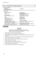
1. Remove locknut (8), washer (9), and screw (12) from frame sill (7). Discard locknut (8).
2. Remove locknut (11), screw (2), and bracket (10) from bracket (3). Discard locknut (11).
NOTE
Assistants will help remove frame sill.
3.
Remove locknut (4), washer (5), screw (6), and frame sill (7) from tank body (l). Discard locknut (4).
15-32
Back to Top

