TM-9-2320-361-34 - Page 347 of 764
TM 9-2320-361-34
15-10.
DISCHARGE
VALVE REPAIR (M50A2)
THIS TASK COVERS:
a. Disassembly
c. Assembly
b.
Cleaning and Inspection
INITIAL SETUP
APPLICABLE MODELS
M50A2
TEST EQUIPMENT
Micrometer (Appendix B, Item 3)
TOOLS
General mechanic’s tool kit
(Appendix B, Item 1)
Handle, socket wrench, 1-in. dr.
(Appendix B, Item 43)
Spring tester (Appendix B, Item 38)
Torque wrench, 1/2-in. dr. (Appendix B, Item 7)
Pipe wrench (Appendix B, Item 39)
2-1/4-in. socket, 1-in. dr. (Appendix B, Item 57)
Adjustable wrench (Appendix B, Item 62)
MATERIALS/PARTS
Packing (Appendix F, Item 179)
Disc
(Appendix F, Item 25)
Cotter pin (Appendix F, Item 8)
Rags (Appendix C, Item 16)
REFERENCES (TM)
TM 9-2320-361-20
TM 9-2320-361-34P
EQUIPMENT CONDITION
Discharge valve removed (TM 9-2320-361-20).
GENERAL SAFETY INSTRUCTIONS
Eye protection must be worn when working with
discharge valve internal spring.
a. Disassembly
WARNING
Discharge valve internal spring is compressed by bonnet. Eye
protection must be worn during bonnet removal from valve housing.
Failure to do so may result in injury to personnel.
1.
2.
3.
4.
5.
6.
7.
8.
9.
10.
11.
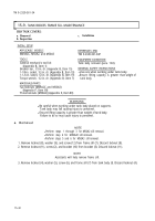
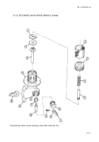
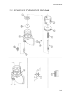
Remove strainer (2) from discharge valve housing (13).
Remove bonnet (3) from valve housing (13) and upper plunger (5).
Remove spring (4) and upper plunger (5) with nut (1), disc (15), and lower plunger (14) from valve
housing (13).
Remove nut (1) and disc (15) from lower plunger (14) and upper plunger (5). Discard disc (15).
Remove upper plunger (5) from lower plunger (14).
Remove cotter pin (8) from lever arm (7) and stem (9). Discard cotter pin (8).
Remove lever arm (7) from stem (9).
Remove plug (6) from valve housing (13) and stem (9).
Remove stem (9) from cam (12) and stem bore (11) of valve housing (13).
Remove cam (12) horn valve housing (13).
Remove packing (10) from stem bore (11). Discard packing (10).
15-36
Back to Top


