TM-9-2320-361-34 - Page 411 of 764
TM 9-2320-361-34
15-25. BLACKOUT SWITCH REPLACEMENT
THIS TASK COVERS:
a. Removal
b.
Installation
lNITIAL SETUP
APPLICABLE MODELS
MATERIALS/PARTS
M185A3 and M109A3
Six lockwashers (Appendix F, Item 151)
TEST
EQUIPMENT
Multimeter (Appendix B, Item 3)
TOOLS
General mechanic’s tool kit
(Appendix B, Item
1)
Tool kit, electrical (Appendix B, Item 2)
Pipe wrench (Appendix B, Item 39)
REFERENCES (TM)
TM 9-2320-361-10
TM 9-2320-361-20
TM 9-2320-361-34P
EQUIPMENT CONDITION
●
Parking brake set (TM 9-2320-361-10).
●
Battery ground cable disconnected
(TM9-2320-361-20).
a. Removal
NOTE
Tag wires, leads, and terminals for installation.
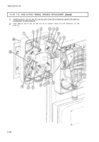
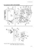
1. Remove four screws (3), lockwashers (4), and cover (1) from blackout switch (2). Discard lock-
washers (4).
2. Remove five screws (8), lockwashers (7), and wires (5), (6), (9), (10), (11), (12), and (13) from blackout
switch (2).
3. Remove bushing (16) from nipple (15).
4.
Remove two nuts (17), lockwashers (18), and blackout switch (2) from mounting bracket (14).
Discard lockwashers (18).
b.
Installation
1. Install blackout switch (2) on mounting bracket (14) with two new lockwashers (18) and nuts (17).
2. Install blackout switch (2) on nipple (15) with bushing (16).
3. Install wires (5), (6), (9), (10), (11), and one end of (12) on blackout switch (2) with four lock-
washers (7) and screws (8).
4. Install wire (13) and other end of wire (12) on blackout switch (2) with lockwasher (7) and screw (8).
5.
Install cover (1) on blackout switch (2) with four new lockwashers (4) and screws (3).
15-100
Back to Top

