TM-9-2320-361-34 - Page 465 of 764
TM 9-2320-361-34
15-40. VERTICAL LEVELING WORM GEAR MAINTENANCE (Contd)
b. Disassembly
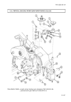
1. Remove two lubrication fittings (8) from shaft (6).
2. Remove two screws (2), lockwashers (3), and setscrews (1) and (4) from housing (5)
lockwashers (3).
NOTE
Measure and record distance shaft extends from worm gear housing.
3. Loosen worm adjusting bearing (12).
Discard
4. Nine woodruff key (9) of shaft(6) with keyway of thrust washer (10). Tap square end of shaft
(6)
and remove sleeve bearing (7), woodruff key (9), and shaft (6) from worm gear housing (5).
5. Remove thrust washer (10), worm gear (11), and adjusting bearing (12) from worm gear housing (5).
6. Remove woodruff key (9) and sleeve bearing(7) from shaft (6). Discard woodruff key (9).
c.
Inspection
1. Check worm gear housing (5) for cracks or other damage. Repair by welding if cracked (TM 9-237).
Replace if damaged.
2. Check all parts for small chips, burrs, and scratches. Raised metal can be removed with a fine mill file.
3. Check worm gear (11) for chipped and broken teeth. Replace if damaged.
4. Inspect adjusting
bearing (12), shaft (6), sleeve bearing(7), and thrust washer (10) for wear or other
damage. Refer to table 15-6, Vertical Leveling Worm Gear Wear Limits, for measurements. Replace
if worm or otherwise damaged.
Table 15-6. Vertical Leveling Worm Gear Wear Limits.
ITEM
WEAR LIMITS/TOLERANCES
NO.
lTEM/POiNT OF MEASUREMENT
INCHES
MILLIMETERS
6
Shaft (diameter)
1.371-1.372
34.82-34.85
7
Sleeve bearing
Inside diameter
1.376-1.378
34.95-35.00
Outside diameter
1.999-2.000
50.77-50.80
10
Thrust washer (thickness)
0.406
10.31
12
Bearing (inside diameter)
1.376-1.378
34.95-35.00
d. Assembly
1. Install adjusting bearing (12) and worm gear (11) in worm gear housing (5).
2. Install thrust washer (10) in worm gear housing (5) so that setscrew notch faces away from worm
gear (11) and keyway alines with keyway of worm gear (11).
3. Install new woodruff key (9) in shaft (6) and install shaft(6) in worm gear housing(5).
4. Set shaft (6) to extend from worm gear housing (5) as previously measured. Finger tighten adjusting
bearing (12).
15-154
Back to Top


