TM-9-2320-365-20-3 - Page 718 of 1268
TM –9-2320-365-20-3
9-2
Change 2
9-2.
DRIVE SHAFT AND UNIVERSAL JOINT REPLACEMENT/REPAIR
This task covers:
a. Removal
b. Disassembly
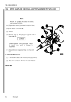
c. Cleaning/Inspection
d. Assembly
e. Installation
f.
Follow-On Maintenance
INITIAL SETUP
Equipment Conditions
Engine shut down (TM 9-2320-366-10-1).
Tools and Special Tools
Tool Kit, Genl Mech (Item 44, Appendix C)
Goggles, Industrial (Item 15, Appendix C)
Hammer, Hand (Item 18, Appendix C)
Materials/Parts
Grease, Automotive and Artillery (GAA) (Item
23, Appendix D)
Materials/Parts (Cont)
Solvent, Dry Cleaning (Item 71, Appendix D)
Rag, Wiping (Item 51, Appendix D)
Spider, Universal Joint, Vehicular (Item 260.1,
Appendix G)
Seal, Shaft (Item 255.2, Appendix G)
Screw, Cap (8 per drive shaft) (Item 237.1, Appendix
G)
Personnel Required
(2)
a.
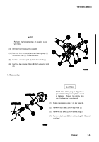
Removal.
(1)
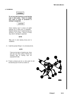
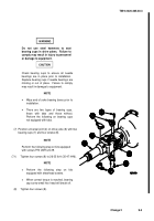
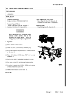
Lift tabs from two bearing cups (1).
(1.1)Remove four screws (2) and two bearing cups (1)
from drive yoke (3).
Discard screws.
(2)
Slide drive shaft (4) from side to side and separate
universal joint (5) from drive yoke (3).
(3)
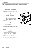
Perform steps (1) and (2) on opposite end of drive
shaft (4).
WARNING
Wear appropriate eye protection when
working under vehicle due to the
possibility of falling debris.
Failure to
comply may result in injury to personnel.
NOTE
•
All drive shafts are removed the same
way.
Front drive shaft shown.
•
There are two types of bearing cups,
those with tabs and those without.
Perform the following step on bearing
cups with tabs.
Back to Top

