TM-9-2320-366-20-1 - Page 911 of 1824
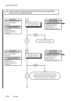
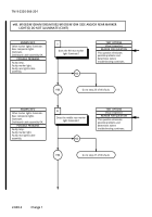
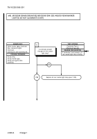
CONTINUITY TEST
Change 1
2-595
TM 9-2320-366-20-1
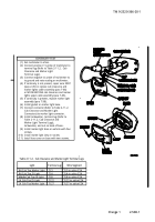
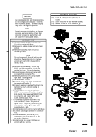
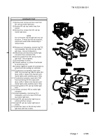
(1) Remove two screws and lens cover from
RH cab top marker light base.
(2) Remove RH cab top marker lamp from
socket.
(3) Remove four screws from RH cab top
marker light base.
Do not let wires slip through hole into cab
structure.
If wires slip into cab structure,
vehicle will need further disassembly to
retrieve wires.
(4) Remove nut, lockwasher, terminal lug TL3,
and lockwasker from RH cab top marker
light base.
Discard lockwashers.
(5) Extend base and disconnect marker light
connector from connector P55.
(6) Remove gasket from RH cab top marker
light base.
Discard gasket.
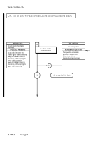
(7) Set multimeter to ohms.
(8) Connect positive (+) probe of multimeter
to terminal lug TL3.
(9) Connect negative (-) probe of multimeter to
ground and note reading on multimeter.
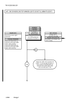
(10) If continuity is not present, repair wire
3097 from terminal lug TL86 to splice E24
(para 2-45) or replace cab clearance and
marker lights cable assembly (para 7-66).
(11) If continuity is present, repair wire 1951
from terminal lug TL74 to splice E23
(para 2-45) or replace cab clearance and
marker lights cable assembly (para 7-66).
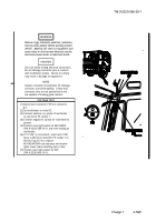
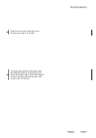
(12) Install gasket on RH cab top marker light
base.
(13) Connect connector P55 to marker light
connector.
(14) Install lockwasher, terminal lug TL3,
lockwasher, and nut on back of RH cab
top marker light base.
(15) Install RH cab top marker light base on
vehicle with four screws.
(16) Install RH cab top marker light lamp in
socket.
(17) Install lens cover on RH cab top marker
light base with two screws.
NOTE
Back to Top

