TM-9-2320-366-20-4 - Page 585 of 1558
TM 9-2320-366-20-4
8-28. M1090/M1094 TRANSMISSION AUXILIARY OIL COOLER HOSE REPLACEMENT
This task covers:
a. Removal (S/N 0001-7161)
b. Installation (S/N 0001-7161
c. Removal (S/N 7162 and higher)
d. Installation (S/N 7162 and higher)
e. Follow-On Maintenance
INITIAL SETUP
Equipment Conditions
Dump body raised to maintenance position (TM 9-
2320-366-10-1).
Batteries disconnected (para 7-57).
Winch control valve assembly removed, if equipped
(para 17-25).
Tools and Special Tools
Goggles, Industrial (Item 15, Appendix C)
Pan, Drain (Item 24, Appendix C)
Tool Kit, Genl Mech (Item 46, Appendix C)
Wrench, Torque 0-175 lb-ft (Item 58, Appendix C)
Materials/Parts
Dispenser, Pressure Sensitive Adhesive Tape
(Item 20, Appendix D)
Cap and Plug Set (Item 14, Appendix D)
Ties, Cable, Plastic (Item 69, Appendix D)
Nut, Self-Locking (6) (Item 155, Appendix G)
Nut, Self-Locking (12) (Item 154, Appendix G)
Packing, Preformed (2) (Item 178.1, Appendix G)
Transmission Auxiliary Oil Cooler Rubber Seal (2)
(Item E-10, Appendix E)
Personnel Required
(2)
WARNING
•
Wear appropriate eye protection when working under vehicle due to the possibility of falling
debris. Failure to comply may result in injury to personnel.
•
Ensure exhaust system is cool before preforming maintenance. Failure to comply may result in
injury to personnel.
NOTE
Vehicle serial numbers 0001 through 7161 may have transmission oil cooler tubes installed. Vehicle
serial numbers 7162 and higher may have transmission oil cooler hoses installed.
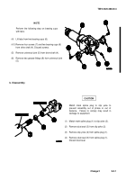
a. Removal (S/N 0001-7161).
CAUTION
Cap or plug hoses and tubes when disconnecting to prevent contamination of transmission oil. Failure
to comply may result in damage to equipment.
NOTE
• Tag hoses, tubes, and connection points prior to disconnecting.
• Remove plastic cable ties as required.
Change 1
8-145
Back to Top

