TM-9-2320-386-24-1-2 - Page 484 of 636
INSTALLATION
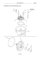
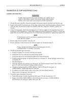
1. Calculate thickness of thrust washer (6):
a. Install spring compressor base on transmission (1) with two screws (3), and tighten down to
keep pressure on end shaft.
b. Position thrust washer selector gauge bar on transmission (1).
c. Install depth gauge so that stem passes through center hole of thrust washer selector gauge
bar and above thrust washer surface of forward clutch housing (2).
d. Measure distance from top of thrust washer gauge bar to thrust washer surface of forward
clutch housing (2). Subtract 1 in. (25.4 mm) of thrust washer selector gauge bar thickness and
record difference using table 1, Oil Pump Thrust Washer Selector.
THRUST WASHER
MARKED
DIMENSION
6831620
0
0.732-0.749 in. (18.61-19.02 mm)
BLACK
6931621
1
0.749-0.765 in. (19.03-19.44 mm)
RED
6831622
2
0.765-0.782 in. (19.44-19.86 mm)
BLUE
6831623
3
0.782-0.798 in. (19.86-20.27 mm)
GREEN
6831624
4
0.798-0.814 in. (20.27-20.69 mm)
BLACK
6831625
5
0.814-0.831 in. (20.69-21.11 mm)
BLACK
Table 1. Oil Pump Thrust Washer Selector.
2
DEPTH
GAUGE
THRUST WASHER
SELECTOR GAUGE BAR
SPRING
COMPRESSOR BASE
1
0374 00-10
TM 9-2320-386-24-1-2
0374 00
TRANSMISSION OIL PUMP MAINTENANCE (Contd)
3
Back to Top

