TM-9-2320-387-24-1 - Page 565 of 1205
TM
9-2320-387-24-l
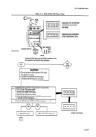
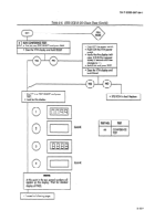
Table 2-6. STE IKE-R
GO-Chain Tests.
INDICATES
VTM IS PROPERLY
I=
1
FORTESTS
CONNECTED
AND READY
GO-CHAIN
INDICATES
GO CONDiTlON
AFTER CONFIDENCE
TESTS
NOTE
Perform all GO steps until a NO-GO condition exists,
then perform the NO-GO
step indicated.
1
V
CAUTION
I
l
Do not connect or disconnect the VTM while
the vehicle is running.
l
Connect DCA cable to the VTM before
connecting to the diagnostic connector.
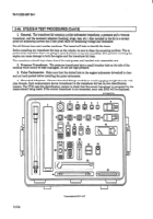
CONNECT VTM TO VEHICLE DIAGNOSTTC
CONNECTOR:
l
PULL OFF the VTM power switch.
l
Connect DCA cable to the VTM.
l
Connect DCA cable
to the vehicle.
l
PUSH ON the VTM power switch.
l
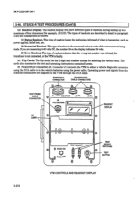
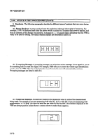
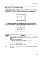
Verify that the display indicates .8.8.8.8
for opproximotely
2 seconds and then changes to - - - -.
l
Does the VTM display .8.8.8.8
and then change to
- - - - ?
II
I
1
l
Proceed to step 3.
1
1
l
Proceed to following page.
-27’
I
J
J
AFTER
2 SECONDS
2-519
Back to Top

