TM-9-2320-387-24-1 - Page 556 of 1205
TM
9-2320.387.24- 1
1 2-46.
STE/ICE-R TEST PROCEDURES
(Cont’d)
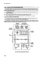
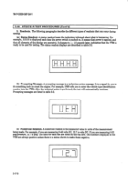
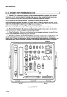
(d) Readout Display. The
readout display will show different types of readouts during testing up to a
maximum of four characters (for example, .8.8.8.8). The types of readouts are described in detail in paragraph
3andaresumma rized as follows:
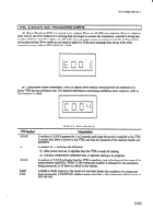
(1) Status Readout. This type of readout keeps the technician informed of what is happening, such as
power applied, failed test, etc.
(2) Numerical Readout. This type of readout is the measured value in units of the measurement being
made. If you are measurin g O-45 volts DC, the number 24 on the display indicates 24 volts.
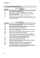
(3)
E&-or
Readout. This type of readout indicates that the wrong t&t number was selected, the
transducer is not connected, or the VTM is faulty.
(e) Flip Cards. The flip cards list the 2-digit test number system for selecting the various tests. The
cards also summarize the test and operating instructions contained herein.
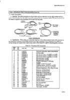
(0 Power/DCA
Connector Jl.
Connector Jl connects the VI’h4 to either a vehicle diagnostic connector
using the DCA cable or to the vehicle batteries using the power cable. Operating power and signals from the
installed transducers are supplied to the VTM through the DCA cable.
POWEWDCA
TRANSDUCER
CONNECTOR
CABLE CONNECTORS
/
I
h
I
/\
\
TEST PROBE
CABLE
CONNECTOR
,
FLIP
-sc
@
PUSHON
VTM
CONTROLS
AND READOUT
DISPLAY
/
READOUT
DISPLAY
-
szI!T
SWITCHES
-
TEST
BUTTON
2-510
Back to Top

