TM-9-2320-387-24-1 - Page 549 of 1205
TM 9-2320-387-24-l
1 2-46.
STE/ICE-R
TEST PROCEDURES
(Cont’d)
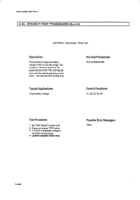
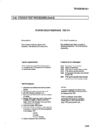
STARTER CIRCUIT RESISTANCE
TEST #74
Description:
Pm-Test Procedures:
This procedure measures
starter circuit
resistance. Test requires DCA hookup only.
Run confidence
test. Warm up engine to
operating
temperature.
Turn off all electrical
accessories.
Typical Applications:
Possible Error Messages:
Check resistance of complete starting system
in Cl engines with VTM powered from batteries
of vehicle being tested.
E002
Transducer
not connected.
E005
Offset not performed.
E008
VTM does not detect battery voltage.
E013
VTM cannot use data received.
E020
No first-peak information was detected
by the VTM.
E021
VTM cannot calculate result because
current is over current probe’s range.
Test Procedure:
1.
2.
3.
4.
5.
6.
7.
Disconnect fuel solenoid wire 54A to prevent
starting.
Make sure all vehicle accessories
are off.
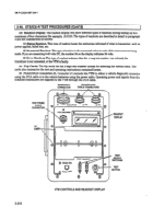
Set TEST SELECT switches to 74.
Press and hold TEST button until CAL appears
on display.
Release TEST button and wait for offset value
to appear on display. If offset is within the
range -150 to 150, proceed. If not, go to DCA
Troubleshooting
Procedure.
Press and release TEST button.
When GO appears on display, crank engine for
2 seconds or until one of the following appears
on the display: Off
.9.9.9.9
A number
An error message
8. Observe displayed value (milliohms).
NOTES:
If .9.9.9.9 is displayed,
the starter circuit
resistance
value was too high and cannot
be measured
with VTM.
If EO13 is displayed,
check battery
connections
and correct as necessary.
Repeat Step 6. If E013 persists after 3
tests, VTM cannot perform test.
2-503
Back to Top

